Nissan Murano Z50 (2006 year). Manual - part 51
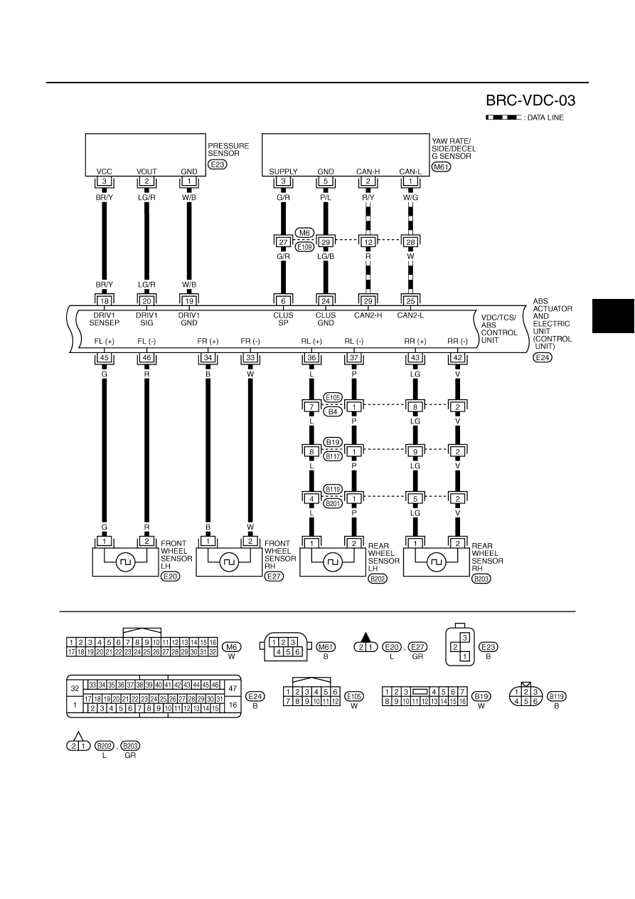
TROUBLE DIAGNOSIS
BRC-61
[VDC/TCS/ABS]
C
D
E
G
H
I
J
K
L
M
A
B
BRC
Revision: 2006 August
2006 Murano
TFWB0039E
|
|
|
TROUBLE DIAGNOSIS BRC-61 [VDC/TCS/ABS] C D E G H I J K L M A B BRC Revision: 2006 August 2006 Murano TFWB0039E |