Nissan Murano Z50 (2006 year). Manual - part 46
BRAKE MASTER CYLINDER
BR-19
C
D
E
G
H
I
J
K
L
M
A
B
BR
Revision: 2006 August
2006 Murano
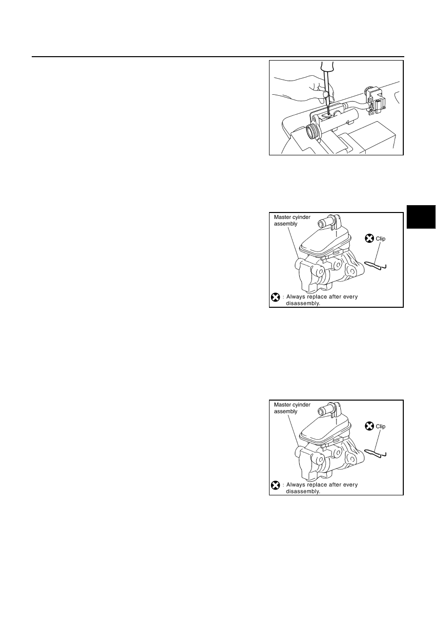
6.
Using a pin punch [commercial service tool: diameter approx. 4
mm (0.16 in)], insert the reservoir tank mounting pin into the pin
hole so that the attachment side and the opposite side are iden-
tical.
CAUTION:
Do not reuse reservoir tank grommet and mounting pin.
WITH VDC MODELS
Disassembly
CAUTION:
●
Master cylinder can not be disassembled.
●
Remove the reservoir tank only when absolutely necessary.
1.
Remove clip.
2.
Remove reservoir tank and grommet from cylinder body.
Assembly
CAUTION:
●
Do not use mineral oils such as kerosene, gasoline during the cleaning and assembly process.
●
Do not drop parts. If a part is dropped, do not use it.
1.
Apply brake fluid the grommet and attach to the cylinder body.
CAUTION:
Do not reuse the grommet.
2.
Install reservoir tank onto the cylinder body.
3.
Insert the clip.
PFIA0439E
PFIA0424E
PFIA0424E