Nissan Murano Z50 (2006 year). Manual - part 39
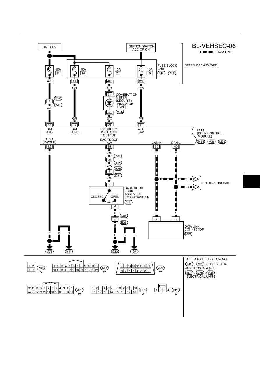
VEHICLE SECURITY (THEFT WARNING) SYSTEM
BL-219
C
D
E
F
G
H
J
K
L
M
A
B
BL
Revision: 2006 August
2006 Murano
Wiring Diagram -VEHSEC- / Without Intelligent Key
NIS0019B
TIWB0790E
|
|
|
VEHICLE SECURITY (THEFT WARNING) SYSTEM BL-219 C D E F G H J K L M A B BL Revision: 2006 August 2006 Murano Wiring Diagram -VEHSEC- / Without Intelligent Key NIS0019B TIWB0790E |