Nissan Murano Z50 (2006 year). Manual - part 36


  Index      Manuals     Nissan Murano Z50 (2006 year) - Service and Repair Manual


Search            copyright infringement  


Content      ..     34      35      36      37     ..


Nissan Murano Z50 (2006 year). Manual - part 36


INTELLIGENT KEY SYSTEM

BL-171

C

D

E

F

G

H

J

K

L

M

A

B

BL

Revision: 2006 August

2006 Murano

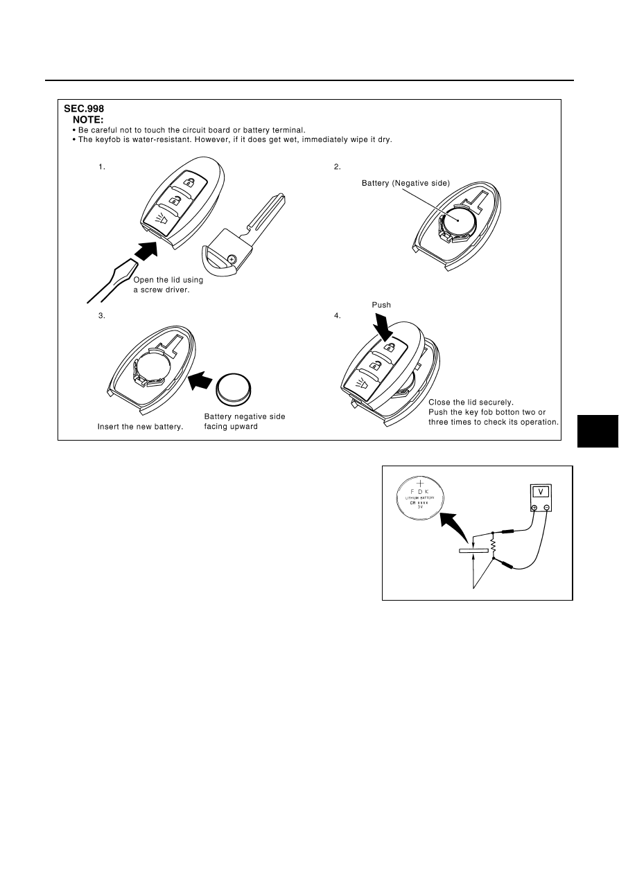
Intelligent Key Battery Replacement

NIS0018E

INTELLIGENT KEY BATTERY INSPECTION

Check by connecting a resistance (approximately 300

) so that the

current value becomes about 10 mA.

PIIB5065E

Standard

: Approx. 2.5 - 3.0V

OCC0607D

BL-172

DOOR

Revision: 2006 August

2006 Murano

DOOR

PFP:80100

Fitting Adjustment

NIS0018F

FRONT DOOR
Longitudinal Clearance and Surface Height Adjustment at Front End

1.

Loosen the hinge mounting bolts. Raise the front door at rear end to adjust.

REAR DOOR
Longitudinal Clearance and Surface Height Adjustment at Front End

1.

Remove the center pillar upper garnish and center pillar lower garnish. Refer to 

EI-32, "BODY SIDE

TRIM"

   .

2.

Accessing from inside the vehicle, loosen the mounting nuts. Open the rear door, and raise the rear door
at rear end to adjust.

1.

Front fender

2.

Front door outer

3.

Rear door outer

PIIA3914E

DOOR

BL-173

C

D

E

F

G

H

J

K

L

M

A

B

BL

Revision: 2006 August

2006 Murano

STRIKER ADJUSTMENT

1.

Adjust the striker so that it becomes parallel with the lock inser-
tion direction.

Removal and Installation of Front Door

NIS0018G

CAUTION:

When removing and installing the front door assembly, support the door with a jack and cloth to
protect the door and body.

Operate with two workers, because of its heavy weight.

When removing and installing front door assembly, be sure to carry out the fitting adjustment
Refer to 

BL-172, "Fitting Adjustment"

 .

Check the hinge rotating part for poor lubrication. If necessary, apply “body grease”.

After installing, check operation.

REMOVAL

1.

Pull the lever and remove the front door harness connector
while removing tabs of door harness connector.

2.

Remove the mounting bolts of the check link on the vehicle.

SIIA0338E

PIIA2514E

PIIA2515E

BL-174

DOOR

Revision: 2006 August

2006 Murano

3.

Remove the door-side hinge mounting nuts, and remove the
door assembly.

INSTALLATION

Install in the reverse order of removal.

Removal and Installation of Rear Door

NIS0018H

CAUTION:

When removing and installing the rear door assembly, support the door with a jack and cloth to
protect the door and body.

Operate with two workers, because of its heavy weight.

When removing and installing rear door assembly, be sure to carry out the fitting adjustment Refer
to 

BL-172, "Fitting Adjustment"

 .

Check the hinge rotating part for poor lubrication. If necessary, apply “body grease”.

After installing, check operation.

REMOVEL

1.

Pull out grommet, and detach rear door harness connector.

2.

Remove the mounting bolts of the check link on the vehicle.

PIIA3925E

PIIA2787E

PIIA2788E

DOOR

BL-175

C

D

E

F

G

H

J

K

L

M

A

B

BL

Revision: 2006 August

2006 Murano

3.

Remove the door-side hinge mounting nuts, and remove the
door assembly.

INSTALLATION

Install in the reverse order of assembly.

Door Weatherstrip

NIS0018I

REMOVAL

1.

Remove the mounting bolts of the check link on the vehicle. Refer to 

BL-173, "Removal and Installation of

Front Door"

   or 

BL-174, "Removal and Installation of Rear Door"

  .

2.

Remove the weatherstrip clips and remove weatherstrip.

INSTALLATION

Install in the reverse order of assembly.

PIIA4412E

1.

Weatherstrip

PIIA3923E

BL-176

FRONT DOOR LOCK

Revision: 2006 August

2006 Murano

FRONT DOOR LOCK

PFP:80502

Component Structure

NIS0018J

Removal and Installation

NIS0018K

REMOVAL

1.

Remove the front door finisher. Refer to

EI-30, "DOOR FINISHER"

   .

2.

Disconnect the inside handle knob cable and lock knob cable
from the back side of the front door finisher.

3.

Remove the front door window and front door module assembly. Refer to

GW-67, "FRONT DOOR GLASS

AND REGULATOR"

   .

4.

Remove door side grommet, and remove door key cylinder
assembly (driver side) and outside handle escutcheon (passen-
ger side) bolts (TORX T30) from grommet hole.

CAUTION:

Do not forcibly remove the TORX bolts (T30).

1.

Front gasket

2.

Outside handle

3.

Door key cylinder assembly (Driver 
side)
Outside handle escutcheon (Pas-
senger side)

4.

Rear gasket

5.

Outside handle bracket

6.

Grommet

7.

Key cylinder rod (Driver side only)

8.

Outside handle cable

9.

Door lock assembly

10. Inside handle knob cable

11.

Lock knob cable

12. Inside handle

PIIB4829E

PIIA4014E

PIIA3553E

FRONT DOOR LOCK

BL-177

C

D

E

F

G

H

J

K

L

M

A

B

BL

Revision: 2006 August

2006 Murano

5.

Reach to separate the key cylinder rod connection (on the handle). 

6.

Disconnect door key cylinder switch harness connector. 

7.

While pulling the outside handle, remove door key cylinder
assembly.

8.

Disconnect front door request switch harness connector (wiht Intelligent Key system). 

9.

While pulling outside handle, slide toward rear of vehicle to
remove outside handle.

10. Remove the front gasket and rear gasket.

11. Remove the TORX bolts (T30), remove the door lock assembly.

PIIA3554E

PIIA3555E

PIIA3557E

PIIA1090E

BL-178

FRONT DOOR LOCK

Revision: 2006 August

2006 Murano

12. Remove the TORX bolt (T30) of the outside handle bracket.

13. While pulling outside handle bracket, slide toward rear of vehicle

to remove outside handle bracket.

14. Disconnect the door lock actuator connector and remove the door lock assembly.

15. Reach to separate the outside handle cable connection.

INSTALLATION

Install in the reverse order of removal.

CAUTION:

To install each rod, be sure to rotate the rod holder until a click is felt.

PIIB5076E

PIIA3558E

PIIA5059E

REAR DOOR LOCK

BL-179

C

D

E

F

G

H

J

K

L

M

A

B

BL

Revision: 2006 August

2006 Murano

REAR DOOR LOCK

PFP:82502

Component Structure

NIS0018L

Removal and Installation

NIS0018M

REMOVAL

1.

Remove the rear door finisher. Refer to

EI-30, "DOOR FINISHER"

   .

2.

Disconnect the inside handle knob cable and lock knob cable
from the back side of the rear door finisher.

3.

Remove the rear door sash. Refer to

GW-70, "REAR DOOR GLASS AND REGULATOR"

   .

4.

Remove the rear door window and rear door screen assembly. Refer to

GW-70, "REAR DOOR GLASS

AND REGULATOR"

   .

5.

Remove door side grommet, and remove outside handle escutcheon bolt (TORX T30) from grommet
hole.

1.

Front gasket

2.

Outside handle

3.

Outside handle escutcheon

4.

Rear gasket

5.

Outside handle bracket

6.

Grommet

7.

Outside handle cable

8.

Door lock assembly

9.

Inside handle knob cable

10. Lock knob cable

11.

Inside handle

PIIB4830E

PIIA4014E

BL-180

REAR DOOR LOCK

Revision: 2006 August

2006 Murano

CAUTION:

Do not forcibly remove the TORX bolts (T30).

6.

While pulling the outside handle, remove outside handle
escutcheon.

7.

While pulling outside handle, slide toward rear of vehicle to
remove outside handle.

8.

Remove the front gasket and rear gasket.

PIIA3553E

PIIA6344E

PIIA3555E

PIIA3557E

REAR DOOR LOCK

BL-181

C

D

E

F

G

H

J

K

L

M

A

B

BL

Revision: 2006 August

2006 Murano

9.

Remove the TORX bolts (T30), remove the door lock assembly.

10. Remove the TORX bolt (T30), and remove the outside handle

bracket.

11. While pulling outside handle, slide toward rear of vehicle to

remove outside handle.

12. Disconnect the door lock actuator connector and remove the door lock assembly.

13. Reach to separate outside handle cable connection.

INSTALLATION

Install in the reverse order of removal.

CAUTION:

To install each rod, be sure to rotate the rod holder until a click is felt.

PIIA1090E

PIIB5076E

PIIA3558E

PIIA5059E

BL-182

BACK DOOR

Revision: 2006 August

2006 Murano

BACK DOOR

PFP:90100

Fitting Adjustment

NIS0018N

VERTICAL/LATERAL CLEARANCE ADJUSTMENT

1.

Loosen the back door striker mounting screw, and close the back door lightly.

2.

Adjust the surface height with the bumper rubber (upper/lower).

NOTE:

Rotate the bumper rubber (upper) to adjust the height.

Rotate the TORX (T20) bolt of the bumper rubber (lower) to adjust the height.

3.

After adjusting the surface hight, open the door and tighten the back door striker mounting screw and
bumper rubber (upper) lock nuts to the specified torque.

1.

Bumper rubber (upper)

2.

Bumper rubber (lower)

3.

Back door striker

4.

Screw

PIIA3915E

BACK DOOR

BL-183

C

D

E

F

G

H

J

K

L

M

A

B

BL

Revision: 2006 August

2006 Murano

Back Door Assembly

NIS0018O

REMOVAL

CAUTION:

Before servicing SRS, turn ignition switch OFF, disconnect both battery cables and wait at least 3 min-
utes.

1.

Remove the headlining. Refer to 

EI-35, "Removal and Installation"

 .

2.

Disconnect the back door harness connector.

3.

Remove the high mount stop lamp cover.

4.

Washer hose is separated in the connection part.

5.

Remove the viral tape which tight the back door harness and SRS curtain air bag harness.

6.

Support the back door lock with a proper material to prevent it
from falling.

WARNING:

Body injury may occur if no supporting rod is holding the
back door open when removing the back door stay.

7.

Remove back door stay on back door.

8.

Remove hinge mounting bolts on the back door and remove
back door assembly.

CAUTION:

Do not loosen hinge mounting bolt A and D.

PIIA3916E

PIIA4013E

PIIA3917E

PIIA3918E

BL-184

BACK DOOR

Revision: 2006 August

2006 Murano

INSTALLATION

Install in the reverse order of removal.

CAUTION:

Operate with two workers, because of its heavy weight.

After installing, check operation.

After installing, perform fitting adjustment Refer to 

BL-182, "Fitting Adjustment"

 .

INSPECTION

1.

Check hinges for the following items.

Malfunction noise or door closing and opening effort

Component wear or damage

2.

Apply Grease to the rotating part of the hinge.

Removal and Installation of Back Door Striker

NIS0018P

REMOVAL

1.

Remove luggage finisher lower. Refer to 

EI-37, "Removal and

Installation"

 .

2.

Remove mounting screws, and remove striker from the vehicle.

INSTALLATION

Install in the reverse order of removal.

CAUTION:

After installing, perform fitting adjustment.

Removal and Installation of Back Door Stay

NIS0018Q

REMOVAL

1.

Support the back door lock with a proper material to prevent it
from falling.

WARNING:

Body injury may occur if no supporting rod is holding the
back door open when removing the back door stay.

PIIA3918E

PIIA3920E

PIIA4013E

BACK DOOR

BL-185

C

D

E

F

G

H

J

K

L

M

A

B

BL

Revision: 2006 August

2006 Murano

2.

Remove back door stay on back door.

3.

Remove back door stay assembly bracket adjusting nuts and
remove back door stay assembly.

INSTALLATION

Install in the reverse order of removal.

CAUTION:

After installing, check operation.

Removal and Installation of Back Door Weatherstrip

NIS0018R

REMOVAL

Pull up and remove engagement with body from wetherstrip joint.

CAUTION:

After removal, do not pull strongly on the wetherstrip.

INSTALLATION

1.

Working from the upper section, align weatherstrip mark with vehicle center position mark and install
weatherstrip onto the vehicle.

2.

For the lower section, align the weatherstrip seam with center of the striker.

3.

After installation, pull the weatherstrip gently to ensure that there is no loose section.

PIIA3917E

PIIA3919E

1.

Weatherstrip mark

2.

Weatherstrip 

PIIB2269J

BL-186

BACK DOOR

Revision: 2006 August

2006 Murano

NOTE:
Make sure the weatherstrip is fit tightly at each corner and back door rear plate.

Emergency Unlock Lever

NIS0018S

NOTE:
If the back door cannot be opened with the back door lock opener switch or remote controller to a discharged
battery, follow the next steps.

1.

Remove back door finisher cover.

2.

Move the emergency unlock lever to open the back door.

PIIB4832E


Content      ..     34      35      36      37     ..