Nissan Murano Z50 (2006 year). Manual - part 35
INTELLIGENT KEY SYSTEM
BL-155
C
D
E
F
G
H
J
K
L
M
A
B
BL
Revision: 2006 August
2006 Murano
2.
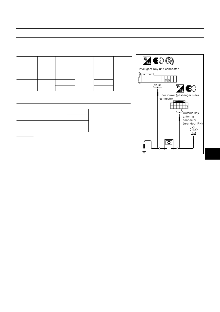
CHECK OUTSIDE KEY ANTENNA CIRCUIT
1.
Disconnect Intelligent Key unit connector and outside key antenna (door mirror) connector.
2.
Check continuity between each outside key antenna harness connector and Intelligent Key unit connec-
tor.
3.
Check continuity between each outside key antenna connector
and ground.
OK or NG
OK
>> GO TO 3.
NG
>> Replace harness between outside key antenna and
Intelligent Key unit.
Item
Connector
Terminal
(Wire color)
Connector
Terminal
(Wire color)
Continuity
Door mirror
(passenger
side)
D32
1 (LG)
M99
37 (LG)
Yes
12 (B/Y)
38 (B/Y)
Rear door
RH
D77
1 (LG)
37 (LG)
2 (B/Y)
38 (B/Y)
Item
Connector
Terminal
Continuity
Door mirror
(passenger side)
D32
1 (LG)
Ground
No
12 (B/Y)
Rear door RH
D77
1 (LG)
2 (B/Y)
PIIB4618E