Nissan Murano Z50 (2006 year). Manual - part 25


  Index      Manuals     Nissan Murano Z50 (2006 year) - Service and Repair Manual


Search            copyright infringement  


Content      ..     23      24      25      26     ..


Nissan Murano Z50 (2006 year). Manual - part 25


BCM (BODY CONTROL MODULE)

BCS-9

C

D

E

F

G

H

I

J

L

M

A

B

BCS

Revision: 2006 August

2006 Murano

CAN Communication Unit

NKS001VH

Refer to 

LAN-32, "CAN Communication Unit"

 .

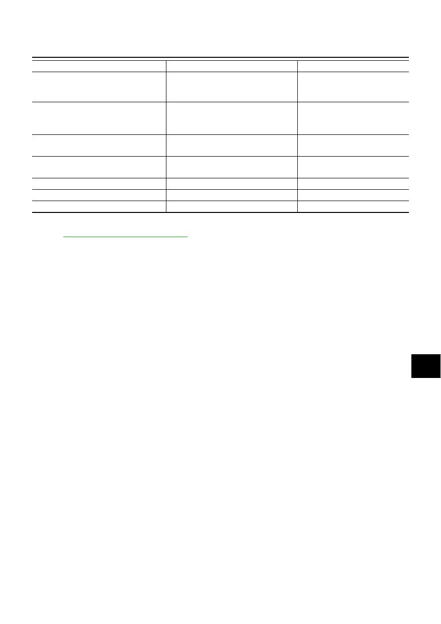
Seat belt warning chime

Combination meter [Seat belt buckle 
(driver side) switch]

Ignition switch

Combination meter
(warning buzzer)

Front wiper and washer system

Combination switch

Combination meter

Ignition switch

IPDM E/R

Rear wiper and washer system

Combination switch

Ignition switch

Rear wiper motor

Rear window defogger

Rear window defogger switch

Ignition switch

IPDM E/R

A/C switch signal

Unified meter and A/C amp.

ECM

Blower fan switch signal

Unified meter and A/C amp.

ECM

Low tire pressure warning system

Remote keyless entry receiver

Combination meter

System

Input

Output

BCS-10

BCM (BODY CONTROL MODULE)

Revision: 2006 August

2006 Murano

Schematic

NKS001VI

TKWB2621E

BCM (BODY CONTROL MODULE)

BCS-11

C

D

E

F

G

H

I

J

L

M

A

B

BCS

Revision: 2006 August

2006 Murano

TKWB2622E

BCS-12

BCM (BODY CONTROL MODULE)

Revision: 2006 August

2006 Murano

CONSULT-II Function (BCM)

NKS001VJ

CONSULT-II can display each diagnostic item using the diagnostic test modes shown following.

CONSULT–II INSPECTION PROCEDURE

Refer to 

GI-38, "CONSULT-II Start Procedure"

 .

ITEMS OF EACH PART

NOTE:
CONSULT-II displays systems equipped in the vehicle.

×

:Applicable

NOTE:
*1: This item is displayed, but should not be used.
*2: This item is displayed, but does not function.

BCM diagnostic test item

Check item, diagnostic test mode

Content

Inspection by part

WORK SUPPORT

Changes setting of each function.

SELF-DIAG RESULTS

BCM performs self-diagnosis of CAN communication.

DATA MONITOR

Displays the input data of BCM in real time.

CAN DIAG SUPPORT MNTR

The result of transmit/receive diagnosis of CAN communication can 
be read.

ACTIVE TEST

Gives a drive signal to a load to check the operation.

ECU PART NUMBER

ECM part number can be read.

CONFIGURATION

(Not be used.)

System and item

CONSULT-II

display

Diagnostic test mode (Inspection by part)

WORK 

SUP-

PORT

SELF

DIAG 

RESULTS

DATA 

MON-

ITOR

CAN DIAG 
SUPPORT 

MNTR

ACTI

VE 

TEST

ECU 

PART 

NUMBER

CON-

FIGU-

RATION

BCM

BCM

×

×

×

×

×

*1

Power door lock system

DOOR LOCK

×

×

×

Rear window defogger

REAR DEFOGGER

×

×

Warning chime

BUZZER

×

×

Room lamp timer

INT LAMP

×

×

×

Headlamp

HEAD LAMP

×

×

×

Wiper

WIPER

×

×

×

Turn signal lamp
Hazard lamp

FLASHER

×

×

Blower fan switch signal
A/C switch signal

AIR CONDITONER

×

Intelligent Key system

INTELLIGENT KEY

×

Combination switch

COMB SW

×

NVIS

IMMU

×

×

Room lamp battery saver

BATTERY SAVER

×

×


×


Trunk lid

TRUNK

*2

×

×

Vehicle security system

THEFT ALM

×

×

×

Retained power control

RETAINED PWR

×

×

×

Oil pressure switch

SIGNAL BUFFER

×

×

Low tire pressure warning system

AIR PRESSURE 
MONITOR

×

×

×

×

Panic system

PANIC ALARM

×

BCM (BODY CONTROL MODULE)

BCS-13

C

D

E

F

G

H

I

J

L

M

A

B

BCS

Revision: 2006 August

2006 Murano

WORK SUPPORT
Operation Procedure

1.

Touch “BCM” on “SELECT TEST ITEM” screen.

2.

Touch “WORK SUPPORT” on “SELECT DIAG MODE” screen.

3.

Touch item on “SELECT WORK ITEM” screen.

4.

Touch “START”.

5.

Touch “CHANGE SET”.

6.

The setting will be changed and “RESETTING COMPLETED” will be displayed.

7.

Touch “END”.

Display Item List

CAN Communication Inspection Using CONSULT-II (Self-Diagnosis)

NKS001VK

1. 

CHECK SELF-DIAGNOSTIC RESULT

CAUTION:

If CONSULT-II is used with no connection of CONSULT-II CONVERTER, malfunctions might be
detected in self-diagnosis depending on control unit which carry out CAN communication. 

1.

Connect to CONSULT-II, and select “BCM” on “SELECT SYSTEM” screen.

2.

Select “BCM control unit ” on “SELECT WORK ITEM” screen, and select “SELF-DIAG RESULTS”.

3.

Check display content in self-diagnostic results.

Contents displayed

No malfunction>>INSPECTION END
Malfunction in CAN communication system>>After printing the monitor items, go to “CAN System”. Refer to

LAN-3, "Precautions When Using CONSULT-II"

 .

Item

Description

RESET SETTING VALUE

Return a value of each system to a default value.

CONSULT-II display code

Diagnosis item

U1000

INITIAL DIAG

TRANSMIT DIAG

ECM

IPDM E/R

METER / M&A

I - KEY

BCS-14

BCM (BODY CONTROL MODULE)

Revision: 2006 August

2006 Murano

Removal and Installation of BCM

NKS001VL

REMOVAL

1.

Remove the Instrument driver lower panel. Refer to 

IP-11,

"Removal and Installation"

 .

2.

Disconnect BCM connector.

3.

Remove screws to remove BCM.

INSTALLATION

Installation is the reverse order of removal.

NOTE:
When replacing BCM perform initialization of NATS system and registration of all NATS ignition key IDs.

SKIA4038E

BL-1

BODY, LOCK & SECURITY SYSTEM

I  BODY

CONTENTS

C

D

E

F

G

H

J

K

L

M

SECTION 

A

B

BL

Revision: 2006 August

2006 Murano

BODY, LOCK & SECURITY SYSTEM

PRECAUTIONS .......................................................... 5

Precautions for Supplemental Restraint System 
(SRS) “AIR BAG” and “SEAT BELT PRE-TEN-
SIONER” .................................................................. 5
Precautions for Work ................................................ 5

PREPARATION ........................................................... 6

Special Service Tools  ............................................... 6
Commercial Service Tools ........................................ 6

SQUEAK AND RATTLE TROUBLE DIAGNOSIS ...... 7

Work Flow  ................................................................ 7

CUSTOMER INTERVIEW ..................................... 7
DUPLICATE THE NOISE AND TEST DRIVE  ....... 8
CHECK RELATED SERVICE BULLETINS  ........... 8
LOCATE THE NOISE AND IDENTIFY THE 
ROOT CAUSE  ...................................................... 8
REPAIR THE CAUSE  ........................................... 8
CONFIRM THE REPAIR  ....................................... 9

Generic Squeak and Rattle Troubleshooting  ........... 9

INSTRUMENT PANEL  .......................................... 9
CENTER CONSOLE ............................................. 9
DOORS ................................................................. 9
TRUNK ................................................................ 10
SUNROOF/HEADLINING ................................... 10
SEATS ................................................................. 10
UNDERHOOD ..................................................... 10

Diagnostic Worksheet  .............................................11

HOOD ....................................................................... 13

Fitting Adjustment  .................................................. 13

LONGITUDINAL AND LATERAL CLEARANCE 
ADJUSTMENT .................................................... 14
FRONT END HEIGHT ADJUSTMENT  ............... 14
SURFACE HEIGHT ADJUSTMENT  ................... 14

Removal and Installation of Hood Assembly .......... 15

REMOVAL ........................................................... 15
INSTALLATION ................................................... 15

Removal and Installation of Hood Lock Control  ..... 16

REMOVAL ........................................................... 16
INSTALLATION ................................................... 17

Hood Lock Control Inspection  ................................ 17

RADIATOR CORE SUPPORT  .................................. 19

Removal and Installation  ........................................ 19

REMOVAL ........................................................... 19
INSTALLATION ................................................... 21

FRONT FENDER  ...................................................... 22

Removal and Installation  ........................................ 22

REMOVAL ........................................................... 22
INSTALLATION ................................................... 22

POWER DOOR LOCK SYSTEM  .............................. 23

Component Parts and Harness Connector Location 

... 23

System Description ................................................. 24

FUEL LID OPERATION ....................................... 25
POWER WINDOW SERIAL LINK  ....................... 26
OUTLINE ............................................................. 26

CAN Communication System Description  .............. 27
CAN Communication Unit ....................................... 27
Schematic / With Intelligent Key  ............................. 28
Wiring Diagram -D/LOCK- / With Intelligent Key  .... 29
Schematic / Without Intelligent Key  ........................ 34
Wiring Diagram -D/LOCK- / Without Intelligent Key ... 35
Terminals and Reference Value for BCM  ............... 39
CONSULT-II Function (BCM)  ................................. 40

CONSULT-II BASIC OPERATION PROCEDURE 

... 40

CONSULT-II APPLICATION ITEMS  .................... 41

Work Flow ............................................................... 42
Trouble Diagnoses Chart by Symptom ................... 42
Power Supply and Ground Circuit Check  ............... 43
Check Door Switch  ................................................. 44

CHECK DOOR SWITCH (EXCEPT BACK DOOR 
SWITCH) ............................................................. 44
CHECK BACK DOOR SWITCH  .......................... 46

Check Key Switch ................................................... 48
Check Door Lock and Unlock Switch  ..................... 50
Check Door Lock Actuator (Driver Side)  ................ 52
Check Door Lock Actuator (Passenger Side and 
Rear LH/RH) ........................................................... 53
Check Door Key Cylinder Switch / Without Intelligent 
Key System  ............................................................ 54
Check Door Key Cylinder Switch / With Intelligent 

BL-2

Revision: 2006 August

2006 Murano

Key System  ............................................................ 55
Check Select Unlock Relay Circuit  ......................... 56
Check Fuel Lid Lock Actuator ................................. 56

REMOTE KEYLESS ENTRY SYSTEM ..................... 58

Component Parts and Harness Connector Location ... 58
System Description ................................................. 59

INPUTS ............................................................... 59
OPERATED PROCEDURE  ................................. 60

CAN Communication System Description  .............. 62
CAN Communication Unit ....................................... 62
Schematic ............................................................... 63
Wiring Diagram — KEYLES— ................................ 64
Terminals and Reference Value for BCM ................ 67
Terminals and Reference Value for IPDM E/R ........ 68
CONSULT-II Function  ............................................. 69
CONSULT-II Inspection Procedure ......................... 69

“MULTI REMOTE ENT”  ....................................... 69

CONSULT-II Application Items  ............................... 70

“MULTI REMOTE CONTENT”  ............................. 70

Work Flow ............................................................... 72
Trouble Diagnosis Chart by Symptom  .................... 73
Check Key Fob Battery ........................................... 74
Check Key Fob Function  ........................................ 74
Check ACC Power Supply Circuit  .......................... 75
Check Door Switch  ................................................. 76

CHECK DOOR SWITCH (EXCEPT BACK DOOR 
SWITCH) ............................................................. 76
CHECK BACK DOOR SWITCH  .......................... 78

Check Key Switch ................................................... 80
Check Remote Keyless Entry Receiver .................. 81
Check IPDM E/R Operation .................................... 84
Check Hazard Function  .......................................... 84
Check Horn Function  .............................................. 84
Check Headlamp Function  ..................................... 84
Check Room Lamp and Ignition Keyhole Illumina-
tion Function  ........................................................... 85
ID Code Entry Procedure  ....................................... 86

KEY FOB ID SET UP WITH CONSULT-II  ........... 86
KEY FOB ID SET UP WITHOUT CONSULT-II .... 88

Key Fob Battery Replacement ................................ 89

INTELLIGENT KEY SYSTEM  ................................... 90

Component Parts and Harness Connector Location ... 90
System Description ................................................. 92

DOOR LOCK/UNLOCK FUNCTION  ................... 93
REMOTE KEYLESS ENTRY FUNCTIONS ......... 97
ENGINE START FUNCTION ............................. 100
WARNING CHIME FUNCTION  ......................... 101
CHANGE SETTINGS FUNCTION ..................... 103
INTELLIGENT KEY REGISTRATION ................ 104
STEERING LOCK UNIT REGISTRATION  ........ 104

CAN Communication System Description  ............ 104
CAN Communication Unit ..................................... 104
Schematic ............................................................. 105
Wiring Diagram — I/KEY—  .................................. 107
Terminals and Reference Value for Intelligent Key 
Unit ....................................................................... 120
Terminals and Reference Value for Steering Lock 
Unit ....................................................................... 122
Terminals and Reference Value for BCM .............. 122

Terminals and Reference Value for IPDM E/R  ......123
Trouble Diagnosis Procedure ................................124

PRELIMINALY CHECK ......................................124
WORK FLOW  ....................................................125

CONSULT-II Functions (INTELLIGENT KEY) .......126
CONSULT-II Inspection Procedure  .......................126

BASIC OPERATION  ..........................................126

CONSULT-II Application Items ..............................127

SELF-DIAGNOSTIC RESULTS  .........................127
DATA MONITOR  ................................................127
WORK SUPPORT  .............................................128
ACTIVE TEST ....................................................129

Trouble Diagnosis Symptom Chart  .......................130

KEY WARNING LAMP ILLUMINATES GREEN .130
KEY WARNING LAMP ILLUMINATES RED ......130
KEY WARNING LAMP DOES NOT ILLUMINATE .131
SELF-DIAGNOSIS RESULTS ARE NOT DIS-
PLAYED .............................................................131
ENGINE START CONDITION CHECK  ..............131
DOOR LOCK/UNLOCK FUNCTION MALFUNC-
TION ..................................................................132
REMOTE KEYLESS ENTRY FUNCTION MAL-
FUNCTION ........................................................133
HAZARD AND HORN REMINDER FUNCTION 
MALFUNCTION .................................................134
POWER WINDOW DOWN FUNCTION MAL-
FUNCTION ........................................................134
WARNING CHIME FUNCTION MALFUNCTION .134
WARNING LAMP FUNCTION MALFUNCTION .136

Check CAN Communication System  ....................137
Check Power Supply and Ground Circuit  .............137
Check Key Switch (Intelligent Key Unit Input) .......138
Check Key Switch (BCM Input) .............................139
Check Ignition Knob Switch  ..................................140
Check Door Switch  ...............................................142

CHECK DOOR SWITCH (EXCEPT BACK DOOR 
SWITCH) ............................................................142
CHECK BACK DOOR SWITCH .........................144

Check Door Request Switch  .................................145
Check Unlock Sensor  ...........................................147
Check Intelligent Key Warning Buzzer (Inside) .....148
Check Intelligent Key Warning Buzzer (ENGINE 
ROOM) ..................................................................149
Check Outside Key Antenna .................................151

CHECK OUTSIDE KEY ANTENNA (DRIVER 
SIDE) .................................................................151
CHECK OUTSIDE KEY ANTENNA (PASSEN-
GER SIDE) .........................................................154
CHECK OUTSIDE KEY ANTENNA (REAR 
BUMPER) ..........................................................156

Check Inside Key Antenna ....................................158
Check Steering Lock Unit ......................................159
Check Stop Lamp Switch  ......................................161
Check Park Position Switch  ..................................162
Check Select Unlock Relay ...................................164
Check “P-SHIFT” Warning Lamp  ..........................165
Check “KEY” Warning Lamp (RED)  ......................167
Check “KEY” Warning Lamp (GREEN) .................168
Check Hazard Function  ........................................169

BL-3

C

D

E

F

G

H

J

K

L

M

A

B

BL

Revision: 2006 August

2006 Murano

Check Horn Function  ........................................... 169
Check IPDM E/R Operation  ................................. 170
Removal and Installation of Intelligent Key Unit  ... 170

REMOVAL ......................................................... 170
INSTALLATION ................................................. 170

Intelligent Key Battery Replacement  .................... 171

INTELLIGENT KEY BATTERY INSPECTION ... 171

DOOR ..................................................................... 172

Fitting Adjustment  ................................................ 172

FRONT DOOR  .................................................. 172
REAR DOOR  .................................................... 172
STRIKER ADJUSTMENT  ................................. 173

Removal and Installation of Front Door ................ 173

REMOVAL ......................................................... 173
INSTALLATION ................................................. 174

Removal and Installation of Rear Door  ................ 174

REMOVEL ......................................................... 174
INSTALLATION ................................................. 175

Door Weatherstrip  ................................................ 175

REMOVAL ......................................................... 175
INSTALLATION ................................................. 175

FRONT DOOR LOCK  ............................................. 176

Component Structure  ........................................... 176
Removal and Installation  ...................................... 176

REMOVAL ......................................................... 176
INSTALLATION ................................................. 178

REAR DOOR LOCK  ............................................... 179

Component Structure  ........................................... 179
Removal and Installation  ...................................... 179

REMOVAL ......................................................... 179
INSTALLATION ................................................. 181

BACK DOOR  .......................................................... 182

Fitting Adjustment  ................................................ 182

VERTICAL/LATERAL CLEARANCE ADJUST-
MENT ................................................................ 182

Back Door Assembly  ............................................ 183

REMOVAL ......................................................... 183
INSTALLATION ................................................. 184
INSPECTION .................................................... 184

Removal and Installation of Back Door Striker  ..... 184

REMOVAL ......................................................... 184
INSTALLATION ................................................. 184

Removal and Installation of Back Door Stay  ........ 184

REMOVAL ......................................................... 184
INSTALLATION ................................................. 185

Removal and Installation of Back Door Weatherstrip 

. 185

REMOVAL ......................................................... 185
INSTALLATION ................................................. 185

Emergency Unlock Lever  ..................................... 186

BACK DOOR LOCK ASSEMBLY  .......................... 187

Removal and Installation of Back Door Lock  ....... 187

REMOVAL ......................................................... 187
INSTALLATION ................................................. 187
INSPECTION .................................................... 187

Removal and Installation of Back Door Opener 
Switch ................................................................... 188

REMOVAL ......................................................... 188
INSTALLATION ................................................. 188

BACK DOOR OPENER  .......................................... 189

Component Parts and Harness Connector Location 

. 189

System Description / Without Intelligent Key ........ 189
System Description / With Intelligent Key ............. 190

INTELLIGENT KEY OPERATION  ..................... 191

Schematic / With Intelligent Key  ........................... 192
Wiring Diagram —B/DOOR— / With Intelligent Key .193
Wiring Diagram —B/DOOR— / Without Intelligent 
Key ....................................................................... 196
Terminals and Reference Value for BCM  ............. 198
Terminals and Reference Value for INTELLIGENT 
KEY UNIT  ............................................................. 198
Trouble Diagnosis ................................................. 199

BACK DOOR DOSE NOT OPEN WITH BACK 
DOOR OPENER SWITCH / WITHOUT INTEL-
LIGENT KEY SYSTEM  ..................................... 199
BACK DOOR DOSE NOT OPEN WITH BACK 
DOOR OPENER SWITCH / WITH INTELLIGENT 
KEY SYSTEM  ................................................... 203
BACK DOOR DOSE NOT OPEN WITH BACK 
DOOR REQUEST SWITCH  .............................. 206

VEHICLE SECURITY (THEFT WARNING) SYSTEM .207

Component Parts and Harness Connector Location 

. 207

System Description ............................................... 209

DESCRIPTION .................................................. 209
POWER SUPPLY AND GROUND  .................... 210
INITIAL CONDITION TO ACTIVATE THE SYS-
TEM ................................................................... 210
VEHICLE SECURITY SYSTEM ALARM OPER-
ATION ................................................................ 210
VEHICLE SECURITY SYSTEM DEACTIVATION 

. 211

PANIC ALARM OPERATION  ............................ 211

CAN Communication System Description  ............ 211
CAN Communication Unit ..................................... 211
Schematic / With Intelligent Key  ........................... 212
Wiring Diagram -VEHSEC- / With Intelligent Key . 213
Schematic / Without Intelligent Key  ...................... 218
Wiring Diagram -VEHSEC- / Without Intelligent Key .219
Terminals and Reference Value for BCM  ............. 224
Terminals and Reference Value for IPDM E/R  ..... 224
CONSULT-II Function ........................................... 225

CONSULT-II INSPECTION PROCEDURE ........ 225
CONSULT-II APPLICATION ITEM  .................... 226

Trouble Diagnosis ................................................. 227

WORK FLOW  .................................................... 227

Preliminary Check  ................................................ 228
Symptom Chart ..................................................... 229
Diagnostic Procedure 1  ........................................ 230

1 – 1 DOOR SWITCH CHECK  .......................... 230
1 – 2 BACK DOOR SWITCH CHECK  ............... 232

Diagnostic Procedure 2  ........................................ 234

SECURITY INDICATOR LAMP CHECK  ........... 234

Diagnostic Procedure 3  ........................................ 235

FRONT DOOR KEY CYLINDER SWITCH 
CHECK .............................................................. 235

Diagnostic Procedure 4  ........................................ 235

VEHICLE SECURITY HORN ALARM CHECK . 235

Diagnostic Procedure 5  ........................................ 235

VEHICLE SECURITY HEADLAMP ALARM 

BL-4

Revision: 2006 August

2006 Murano

CHECK .............................................................. 235

Diagnostic Procedure 6  ........................................ 235

DOOR LOCK AND UNLOCK SWITCH CHECK .235

NVIS (NISSAN VEHICLE IMMOBILIZER SYSTEM-
NATS) ...................................................................... 236

Component Parts and Harness Connector Location .236
System Description ............................................... 236

DESCRIPTION .................................................. 236
SECURITY INDICATOR  .................................... 237

System Composition ............................................. 238
ECM Re-communicating Function  ........................ 238
Wiring Diagram — NATS —/With Intelligent Key 
System .................................................................. 239
Wiring Diagram — NATS —/Without Intelligent Key 
System .................................................................. 241
Terminals and Reference Value for Steering Lock 
Unit/With Intelligent Key System  .......................... 242
Terminals and Reference Value for Intelligent Key 
Unit/With Intelligent Key System  .......................... 242
Terminals and Reference Value for BCM .............. 243
CONSULT-II Function  ........................................... 243

CONSULT-II INSPECTION PROCEDURE ........ 243
CONSULT-II DIAGNOSTIC TEST MODE FUNC-
TION .................................................................. 244
HOW TO READ SELF-DIAGNOSTIC RESULTS .245
NVIS (NATS) SELF-DIAGNOSTIC RESULTS 
ITEM CHART ..................................................... 245

Trouble Diagnosis Procedure/With Intelligent Key 
System .................................................................. 246

PRELIMINALY CHECK  ..................................... 246
WORK FLOW  .................................................... 247

Trouble Diagnosis Procedure/Without Intelligent 
Key System  .......................................................... 248

WORK FLOW  .................................................... 248

Trouble Diagnoses Symptom Chart ...................... 249

SELF-DIAGNOSIS RELATED ITEM .................. 249

Security Indicator Inspection  ................................ 249

NON SELF-DIAGNOSIS RELATED ITEM ......... 249

Diagnostic Procedure 1  ........................................ 250
Diagnostic Procedure 2  ........................................ 252
Diagnostic Procedure 3  ........................................ 253
Diagnostic Procedure 4  ........................................ 255
Diagnostic Procedure 5  ........................................ 256
Diagnostic Procedure 6  ........................................ 257
How to Replace NATS Antenna Amp.  .................. 258

INTEGRATED HOMELINK TRANSMITTER ........... 259

Wiring Diagram —TRNSCV—  ..............................259
Trouble Diagnoses  ................................................260

DIAGNOSTIC PROCEDURE .............................260

BODY REPAIR  ........................................................262

Body Exterior Paint Color ......................................262
Body Component Parts  .........................................263

UNDERBODY COMPONENT PARTS  ...............263
BODY COMPONENT PARTS ............................265

Corrosion Protection  .............................................267

DESCRIPTION ..................................................267
ANTI-CORROSIVE WAX  ...................................268
UNDERCOATING ..............................................269
STONE GUARD COAT  ......................................270

Body Sealing .........................................................271

DESCRIPTION ..................................................271

Body Construction .................................................274

BODY CONSTRUCTION ...................................274

Body Alignment .....................................................275

BODY CENTER MARKS  ...................................275
PANEL PARTS MATCHING MARKS  .................276
DESCRIPTION ..................................................277
ENGINE COMPARTMENT  ................................278
UNDERBODY ....................................................280
PASSENGER COMPARTMENT  ........................282
REAR BODY ......................................................284

Handling Precautions for Plastics  .........................286

HANDLING PRECAUTIONS FOR PLASTICS  ..286
LOCATION OF PLASTIC PARTS  ......................287

Precautions in Repairing High Strength Steel  .......289

HIGH STRENGTH STEEL (HSS) USED IN NIS-
SAN VEHICLES .................................................289

Replacement Operations  ......................................292

DESCRIPTION ..................................................292
HOODLEDGE ....................................................295
HOODLEDGE (PARTIAL REPLACEMENT)  ......296
FRONT SIDE MEMBER  ....................................297
FRONT SIDE MEMBER (PARTIAL REPLACE-
MENT) ................................................................299
FRONT PILLAR  .................................................300
CENTER PILLAR ...............................................302
OUTER SILL  ......................................................304
REAR FENDER  .................................................306
REAR PANEL  ....................................................308
REAR FLOOR REAR .........................................309
REAR SIDE MEMBER EXTENSION  ................. 311

PRECAUTIONS

BL-5

C

D

E

F

G

H

J

K

L

M

A

B

BL

Revision: 2006 August

2006 Murano

PRECAUTIONS

PFP:00001

Precautions for Supplemental Restraint System (SRS) “AIR BAG” and “SEAT 
BELT PRE-TENSIONER”

NIS0015N

The Supplemental Restraint System such as “AIR BAG” and “SEAT BELT PRE-TENSIONER”, used along
with a front seat belt, helps to reduce the risk or severity of injury to the driver and front passenger for certain
types of collision. This system includes seat belt switch inputs and dual stage front air bag modules. The SRS
system uses the seat belt switches to determine the front air bag deployment, and may only deploy one front
air bag, depending on the severity of a collision and whether the front occupants are belted or unbelted.
Information necessary to service the system safely is included in the SRS and SB section of this Service Man-
ual.

WARNING:

To avoid rendering the SRS inoperative, which could increase the risk of personal injury or death
in the event of a collision which would result in air bag inflation, all maintenance must be per-
formed by an authorized NISSAN/INFINITI dealer.

Improper maintenance, including incorrect removal and installation of the SRS, can lead to per-
sonal injury caused by unintentional activation of the system. For removal of Spiral Cable and Air
Bag Module, see the SRS section.

Do not use electrical test equipment on any circuit related to the SRS unless instructed to in this
Service Manual. SRS wiring harnesses can be identified by yellow and/or orange harnesses or
harness connectors.

Precautions for Work

NIS0015O

After removing and installing the opening/closing parts, be sure to carry out fitting adjustments to check
their operation.

Check the lubrication level, damage, and wear of each part. If necessary, grease or replace it.

BL-6

PREPARATION

Revision: 2006 August

2006 Murano

PREPARATION

PFP:00002

Special Service Tools

NIS0015Q

The actual shapes of Kent-Moore tools may differ from those of special service tools illustrated here.

Commercial Service Tools

NIS0015R

Tool number
(Kent-Moore No.)
Tool name

Description

(J-39570)
Chassis ear

Locating the noise

(J-43980)
NISSAN Squeak and 
Rattle Kit

Repairing the cause of noise

SIIA0993E

SIIA0994E

Tool name

Description

Engine ear

Locating the noise

SIIA0995E

SQUEAK AND RATTLE TROUBLE DIAGNOSIS

BL-7

C

D

E

F

G

H

J

K

L

M

A

B

BL

Revision: 2006 August

2006 Murano

SQUEAK AND RATTLE TROUBLE DIAGNOSIS

PFP:00000

Work Flow

NIS0015S

CUSTOMER INTERVIEW

Interview the customer if possible, to determine the conditions that exist when the noise occurs.Use the Diag-
nostic Worksheet during the interview to document the facts and conditions when the noise occurs and any
customer's comments; refer to 

BL-11, "Diagnostic Worksheet"

 . This information is necessary to duplicate the

conditions that exist when the noise occurs.

The customer may not be able to provide a detailed description or the location of the noise. Attempt to
obtain all the facts and conditions that exist when the noise occurs (or does not occur).

If there is more than one noise in the vehicle, be sure to diagnose and repair the noise that the customer
is concerned about. This can be accomplished by test driving the vehicle with the customer.   

After identifying the type of noise, isolate the noise in terms of its characteristics. The noise characteristics
are provided so the customer, service adviser and technician are all speaking the same language when
defining the noise.

Squeak —(Like tennis shoes on a clean floor)
Squeak characteristics include the light contact/fast movement/brought on by road conditions/hard sur-
faces=higher pitch noise/softer surfaces=lower pitch noises/edge to surface=chirping 

Creak—(Like walking on an old wooden floor)
Creak characteristics include firm contact/slow movement/twisting with a rotational movement/pitch
dependent on materials/often brought on by activity.

Rattle—(Like shaking a baby rattle)
Rattle characteristics include the fast repeated contact/vibration or similar movement/loose parts/missing
clip or fastener/incorrect clearance.

Knock —(Like a knock on a door)
Knock characteristics include hollow sounding/sometimes repeating/often brought on by driver action.

Tick—(Like a clock second hand)
Tick characteristics include gentle contacting of light materials/loose components/can be caused by driver
action or road conditions.

Thump—(Heavy, muffled knock noise)
Thump characteristics include softer knock/dead sound often brought on by activity.

Buzz—(Like a bumble bee)
Buzz characteristics include high frequency rattle/firm contact.

Often the degree of acceptable noise level will vary depending upon the person. A noise that you may
judge as acceptable may be very irritating to the customer.

Weather conditions, especially humidity and temperature, may have a great effect on noise level.

SBT842

BL-8

SQUEAK AND RATTLE TROUBLE DIAGNOSIS

Revision: 2006 August

2006 Murano

DUPLICATE THE NOISE AND TEST DRIVE

If possible, drive the vehicle with the customer until the noise is duplicated. Note any additional information on
the Diagnostic Worksheet regarding the conditions or location of the noise. This information can be used to
duplicate the same conditions when you confirm the repair.
If the noise can be duplicated easily during the test drive, to help identify the source of the noise, try to dupli-
cate the noise with the vehicle stopped by doing one or all of the following:
1) Close a door.
2) Tap or push/pull around the area where the noise appears to be coming from.
3) Rev the engine.
4) Use a floor jack to recreate vehicle “twist”.
5) At idle, apply engine load (electrical load, half-clutch on M/T model, drive position on A/T model).
6) Raise the vehicle on a hoist and hit a tire with a rubber hammer.

Drive the vehicle and attempt to duplicate the conditions the customer states exist when the noise occurs.

If it is difficult to duplicate the noise, drive the vehicle slowly on an undulating or rough road to stress the
vehicle body.

CHECK RELATED SERVICE BULLETINS

After verifying the customer concern or symptom, check ASIST for Technical Service Bulletins (TSBs) related
to that concern or symptom.
If a TSB relates to the symptom, follow the procedure to repair the noise.

LOCATE THE NOISE AND IDENTIFY THE ROOT CAUSE

1.

Narrow down the noise to a general area. To help pinpoint the source of the noise, use a listening tool
(Chassis Ear: J-39570, Engine Ear and mechanics stethoscope).

2.

Narrow down the noise to a more specific area and identify the cause of the noise by:

removing the components in the area that you suspect the noise is coming from.
Do not use too much force when removing clips and fasteners, otherwise clips and fastener can be broken
or lost during the repair, resulting in the creation of new noise.

tapping or pushing/pulling the component that you suspect is causing the noise.
Do not tap or push/pull the component with excessive force, otherwise the noise will be eliminated only
temporarily.

feeling for a vibration with your hand by touching the component(s) that you suspect is (are) causing the
noise.

placing a piece of paper between components that you suspect are causing the noise.

looking for loose components and contact marks.
Refer to 

BL-9, "Generic Squeak and Rattle Troubleshooting"

 .

REPAIR THE CAUSE 

If the cause is a loose component, tighten the component securely.

If the cause is insufficient clearance between components:

separate components by repositioning or loosening and retightening the component, if possible.

insulate components with a suitable insulator such as urethane pads, foam blocks, felt cloth tape or ure-
thane tape. A Nissan Squeak and Rattle Kit (J-43980) is available through your authorized Nissan Parts
Department.

CAUTION:

Do not use excessive force as many components are constructed of plastic and may be damaged.
NOTE:
Always check with the Parts Department for the latest parts information.
The following materials are contained in the Nissan Squeak and Rattle Kit (J-43980). Each item can be
ordered separately as needed.
URETHANE PADS [1.5 mm (0.059 in) thick]
Insulates connectors, harness, etc.
76268-9E005: 100 

×

 135 mm (3.94 

×

 5.31 in)/76884-71L01: 60 

×

 85 mm (2.36 

×

 3.35 in)/76884-71L02: 15 

×

25 mm (0.59  

×

  0.98 in)

INSULATOR (Foam blocks)
Insulates components from contact.Can be used to fill space behind a panel.
73982-9E000: 45 mm (1.77 in) thick, 50 

×

 50 mm (1.97 

×

 1.97 in)/73982-50Y00: 10 mm (0.39 in) thick, 50

×

 50 mm (1.97 

×

 1.97 in)

SQUEAK AND RATTLE TROUBLE DIAGNOSIS

BL-9

C

D

E

F

G

H

J

K

L

M

A

B

BL

Revision: 2006 August

2006 Murano

INSULATOR (Light foam block)
80845-71L00: 30 mm (1.18 in) thick, 30 

×

 50 mm (1.18

×

1.97 in)

FELT CLOTHTAPE
Used to insulate where movement does not occur. Ideal for instrument panel applications.
68370-4B000: 15 

×

 25 mm (0.59 

×

 0.98 in) pad/68239-13E00: 5 mm (0.20 in) wide tape roll The following

materials, not found in the kit, can also be used to repair squeaks and rattles.
UHMW(TEFLON) TAPE 
Insulates where slight movement is present. Ideal for instrument panel applications.
SILICONE GREASE
Used in place of UHMW tape that will be visible or not fit.
Note: Will only last a few months.
SILICONE SPRAY
Use when grease cannot be applied.
DUCT TAPE
Use to eliminate movement.

CONFIRM THE REPAIR

Confirm that the cause of a noise is repaired by test driving the vehicle. Operate the vehicle under the same
conditions as when the noise originally occurred. Refer to the notes on the Diagnostic Worksheet.

Generic Squeak and Rattle Troubleshooting

NIS0015T

Refer to Table of Contents for specific component removal and installation information.

INSTRUMENT PANEL

Most incidents are caused by contact and movement between:

1.

The cluster lid A and instrument panel

2.

Acrylic lens and combination meter housing

3.

Instrument panel to front pillar garnish

4.

Instrument panel to windshield

5.

Instrument panel mounting pins

6.

Wiring harnesses behind the combination meter 

7.

A/C defroster duct and duct joint

These incidents can usually be located by tapping or moving the components to duplicate the noise or by
pressing on the components while driving to stop the noise. Most of these incidents can be repaired by apply-
ing felt cloth tape or silicon spray (in hard to reach areas). Urethane pads can be used to insulate wiring har-
ness.

CAUTION:

Do not use silicone spray to isolate a squeak or rattle. If you saturate the area with silicone, you will
not be able to recheck the repair.

CENTER CONSOLE

Components to pay attention to include:

1.

Shifter assembly cover to finisher

2.

A/C control unit and cluster lid C

3.

Wiring harnesses behind audio and A/C control unit

The instrument panel repair and isolation procedures also apply to the center console.

DOORS

Pay attention to the:

1.

Finisher and inner panel making a slapping noise

2.

Inside handle escutcheon to door finisher

3.

Wiring harnesses tapping 

4.

Door striker out of alignment causing a popping noise on starts and stops

Tapping or moving the components or pressing on them while driving to duplicate the conditions can isolate
many of these incidents. You can usually insulate the areas with felt cloth tape or insulator foam blocks from
the Nissan Squeak and Rattle Kit (J-43980) to repair the noise.

BL-10

SQUEAK AND RATTLE TROUBLE DIAGNOSIS

Revision: 2006 August

2006 Murano

TRUNK

Trunk noises are often caused by a loose jack or loose items put into the trunk by the owner.
In addition look for:
1.

Trunk lid dumpers out of adjustment

2.

Trunk lid striker out of adjustment 

3.

The trunk lid torsion bars knocking together

4.

A loose license plate or bracket

Most of these incidents can be repaired by adjusting, securing or insulating the item(s) or component(s) caus-
ing the noise.

SUNROOF/HEADLINING

Noises in the sunroof/headlining area can often be traced to one of the following:

1.

Sunroof lid, rail, linkage or seals making a rattle or light knocking noise

2.

Sunvisor shaft shaking in the holder

3.

Front or rear windshield touching headlining and squeaking 

Again, pressing on the components to stop the noise while duplicating the conditions can isolate most of these
incidents. Repairs usually consist of insulating with felt cloth tape.

SEATS

When isolating seat noise it's important to note the position the seat is in and the load placed on the seat when
the noise is present. These conditions should be duplicated when verifying and isolating the cause of the
noise.
Cause of seat noise include: 

1.

Headrest rods and holder 

2.

A squeak between the seat pad cushion and frame 

3.

The rear seatback lock and bracket 

These noises can be isolated by moving or pressing on the suspected components while duplicating the con-
ditions under which the noise occurs. Most of these incidents can be repaired by repositioning the component
or applying urethane tape to the contact area.

UNDERHOOD

Some interior noise may be caused by components under the hood or on the engine wall. The noise is then
transmitted into the passenger compartment.
Causes of transmitted underhood noise include:
1.

Any component mounted to the engine wall

2.

Components that pass through the engine wall

3.

Engine wall mounts and connectors

4.

Loose radiator mounting pins

5.

Hood bumpers out of adjustment 

6.

Hood striker out of adjustment

These noises can be difficult to isolate since they cannot be reached from the interior of the vehicle. The best
method is to secure, move or insulate one component at a time and test drive the vehicle. Also, engine RPM
or load can be changed to isolate the noise. Repairs can usually be made by moving, adjusting, securing, or
insulating the component causing the noise.


Content      ..     23      24      25      26     ..