Nissan Murano Z50 (2006 year). Manual - part 19
INTEGRATED DISPLAY SYSTEM
AV-117
C
D
E
F
G
H
I
J
L
M
A
B
AV
Revision: 2006 August
2006 Murano
Tint Is Strange for The RGB Image
NKS002R2
Symptom: Tint of all RGB images is strange.
1.
CHECK HARNESS
1.
Turn ignition switch OFF.
2.
Disconnect display control unit and display connectors.
3.
Check the malfunctioning circuit according to the symptoms.
●
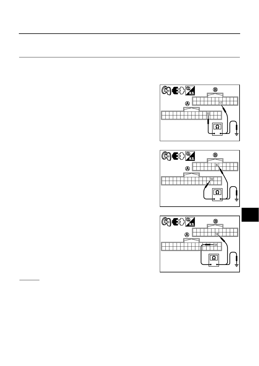
Light blue (Cyan) tinged screen
Check continuity between display control unit harness connector
(A) M43 terminal 50 and display harness connector (B) M38 ter-
minal 17.
Check continuity between display control unit harness connector
(A) M43 terminal 50 and ground.
●
Purple (Magenta) tinged screen
Check continuity between display control unit harness connector
(A) M43 terminal 52 and display harness connector (B) M38 ter-
minal 6.
Check continuity between display control unit harness connector
(A) M43 terminal 52 and ground.
●
Yellow tinged screen
Check continuity between display control unit harness connector
(A) M43 terminal 54 and display harness connector (B) M38 ter-
minal 18.
Check continuity between display control unit harness connector
(A) M43 terminal 54 and ground.
OK or NG
OK
>> GO TO 2.
NG
>> Repair harness or connector.
50 – 17
: Continuity should exist.
50 – Ground
: Continuity should not exist.
SKIB7853E
52 – 6
: Continuity should exist.
52 – Ground
: Continuity should not exist.
SKIB7854E
54 – 18
: Continuity should exist.
54 – Ground
: Continuity should not exist.
SKIB7855E