Nissan Murano Z50 (2006 year). Manual - part 14
AUDIO
AV-37
C
D
E
F
G
H
I
J
L
M
A
B
AV
Revision: 2006 August
2006 Murano
Terminals and Reference Value for A/C and AV Switch
NKS0021R
Terminal
(Wire color)
Item
Signal
input/
output
Condition
Reference value
+
–
Ignition
switch
Operation
1 (Y)
Ground
Battery power supply
Input
OFF
—
Battery voltage
2 (P/B)
Ground
ACC power supply
Input
ACC
—
Battery voltage
3 (R/L)
Ground
Illumination signal
Input
ON
Lighting switch ON
Approx. 12 V
Lighting switch OFF
Approx. 0 V
4 (R/W)
Ground
Illumination control
signal
Input
ON
Illumination control switch is
operated by lighting switch
in ON position
Changes between approx. 0 and
approx. 12 V
5 (B)
Ground
Ground
—
ON
—
Approx. 0 V
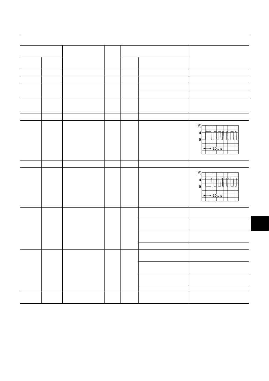
6 (L/G)
Ground
Communication
signal (+)
Input/
Output
ON
—
7
—
Shield
—
—
—
—
8 (L/R)
Ground
Communication
signal (–)
Input/
Output
ON
—
12 (R)
Ground
Remote control A
Input
ON
Press and hold MODE
switch
Approx. 0 V
Press and hold SEEK UP
switch
Approx. 1.7 V
Press and hold VOL UP
switch
Approx. 3.3 V
Except for above
Approx. 5 V
13 (G)
Ground
Remote control B
Input
ON
Press and hold POWER
switch
Approx. 0 V
Press and hold SEEK
DOWN switch
Approx. 1.7 V
Press and hold VOL DOWN
switch
Approx. 3.3 V
Except for above
Approx. 5 V
14 (B/W)
Ground
Remote control
ground
—
ON
—
Approx. 0 V
SKIB7378E
SKIB7379E