Nissan Murano Z50 (2006 year). Manual - part 11


  Index      Manuals     Nissan Murano Z50 (2006 year) - Service and Repair Manual


Search            copyright infringement  


Content      ..     9      10      11      12     ..


Nissan Murano Z50 (2006 year). Manual - part 11


REFRIGERANT LINES

ATC-137

C

D

E

F

G

H

I

K

L

M

A

B

ATC

Revision: 2006 August

2006 Murano

Removal and Installation of Low-pressure Pipe 1 (Engine Compartment)

NJS000C3

REMOVAL

1.

Use a refrigerant collecting equipment (for HFC-134a) to discharge the refrigerant.

2.

Remove cowl top cover. Refer to 

EI-20, "COWL TOP"

 .

3.

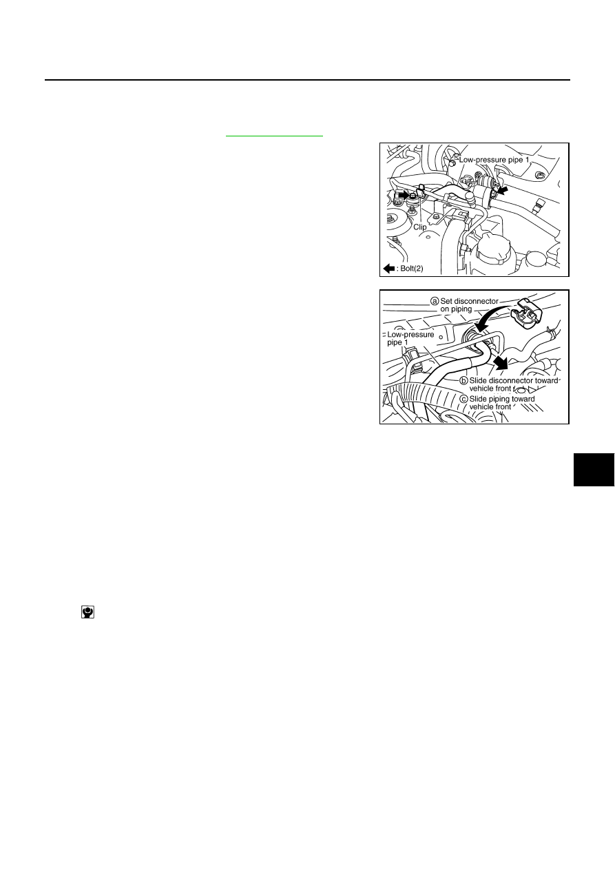
Remove mounting bolts from low-pressure pipe 1 and low-pres-
sure pipe 1 bracket.

4.

Remove high-pressure pipe 1 from clip.

CAUTION:

Cap or wrap the joint of low-pressure pipe 1 and low-pres-
sure flexible hose with suitable material such as vinyl tape
to avoid the entry of air. 

5.

Disconnect one-touch joints.

a.

Set a disconnector (SST: 9253089916) on A/C piping.

b.

Slide a disconnector toward vehicle front until it clicks.

c.

Slide A/C piping toward vehicle front and disconnect it.

6.

Remove low-pressure pipe 1.

CAUTION:

Cap or wrap the joint of low-pressure pipe 1 and 2 with suit-
able material such as vinyl tape to avoid the entry of air.

INSTALLATION

Installation is basically the reverse order of removal.

CAUTION:

Replace O-rings of low-pressure pipe 1 and low-pressure flexible hose with new ones, and then
apply compressor oil to it when installing it.

Female-side piping connection is thin and easy to deform. Slowly insert the male-side piping
straight in axial direction.

Insert piping securely until a click is heard.

After piping connection is completed, pull male-side piping by hand to make sure that connection
does not come loose.

When recharging refrigerant, check for leaks.

RJIA1854E

PJIA0098E

Low-pressure pipe 1 bracket mounting bolt

: 4.2 N·m (0.43 kg-m, 37 in-lb)

ATC-138

REFRIGERANT LINES

Revision: 2006 August

2006 Murano

Removal and Installation of High-pressure Pipe 1 (Engine Compartment)

NJS000C4

REMOVAL

1.

Remove low-pressure pipe 1. Refer to 

ATC-137, "Removal and Installation of Low-pressure Pipe 1

(Engine Compartment)"

 .

2.

Remove radiator reservoir tank. Refer to 

CO-13, "RADIATOR"

 .

3.

Remove IPDM E/R. Refer to 

PG-28, "Removal and Installation of IPDM E/R"

 .

4.

Remove power steering oil tank mounting nuts.

5.

Remove vehicle harness connector from bracket.

6.

Remove high-pressure pipe 1 from clips.

7.

Remove high-pressure flexible hose from vehicle clips.

8.

Disconnect cooling fan connector.

9.

Remove cooling fan harness clips from fan shroud.

10. Remove ground harness terminal mounting bolt.

11. Disconnect one-touch joint of high-pressure pipe 1.

a.

Set a disconnector (SST: 9253089908) on A/C piping.

b.

Slide a disconnector toward vehicle front until it clicks.

c.

Slide A/C piping toward vehicle front and disconnect it.

CAUTION:

Cap or wrap the joint of high-pressure pipe 1 and 2 with
suitable material such as vinyl tape to avoid the entry of air. 

12. Remove mounting bolt, and then remove high-pressure pipe 1.

CAUTION:

Cap or wrap the joint of high-pressure pipe 1 and con-
denser with suitable material such as vinyl tape to avoid the
entry of air. 

INSTALLATION

Installation is basically the reverse order of removal.

RJIA1856E

RJIA1857E

RJIA1855E

RJIA1853E

REFRIGERANT LINES

ATC-139

C

D

E

F

G

H

I

K

L

M

A

B

ATC

Revision: 2006 August

2006 Murano

CAUTION:

Replace O-rings of high-pressure pipe 1 with new ones, and then apply compressor oil to it when
installing it.

Female-side piping connection is thin and easy to deform. Slowly insert the male-side piping
straight in axial direction.

Insert piping securely until a click is heard.

After piping connection is completed, pull male-side piping by hand to make sure that connection
does not come loose.

When recharging refrigerant, check for leaks.

Removal and Installation of Low-pressure Pipe 2 and High-pressure Pipe 2

NJS000C5

REMOVAL

1.

Set the temperature control dial (passenger side) at 18

°

C (60

°

F), and then disconnect the battery cable

from the negative terminal.

2.

Use a refrigerant collecting equipment (for HFC-134a) to discharge the refrigerant.

3.

Remove cowl top cover. Refer to 

EI-20, "COWL TOP"

 .

4.

Remove mounting bolt from low-pressure flexible pipe 1 bracket.

5.

Remove high-pressure pipe 1 from vehicle clips.

6.

Disconnect one-touch joints.

a.

Set a disconnector [high-pressure side (SST: 9253089908), low-
pressure side (SST: 9253089916)] on A/C piping.

b.

Slide a disconnector toward vehicle front until it clicks.

c.

Slide A/C piping toward vehicle front and disconnect it.

CAUTION:

Cap or wrap the joint of low-pressure pipe 1, 2 and high-
pressure pipe 1, 2 with suitable material such as vinyl tape
to avoid the entry of air. 

7.

Remove blower unit. Refer to 

ATC-112, "BLOWER UNIT"

 .

8.

Remove air mix door motor (passenger side), foot duct, heater core cover. Refer to 

ATC-123, "AIR MIX

DOOR MOTOR"

 , 

ATC-129, "Removal of Foot Ducts"

  and 

ATC-124, "HEATER CORE"

 .

9.

Remove mounting screws, and then remove evaporator cover.

RJIA1858E

PJIA0098E

RJIA3992E

ATC-140

REFRIGERANT LINES

Revision: 2006 August

2006 Murano

10. Remove mounting bolt, and then remove low-pressure pipe 2

and high-pressure pipe 2.

CAUTION:

Cap or wrap the joint of evaporator, low-pressure pipe 2 and
high-pressure pipe 2 with suitable material such as vinyl
tape to avoid the entry of air. 

INSTALLATION

Installation is basically the reverse order of removal.

CAUTION:

Replace O-rings of low-pressure pipe 1, 2 and high-pressure pipe 1, 2 with new ones, and then
apply compressor oil to it when installing it.

Female-side piping connection is thin and easy to deform. Slowly insert the male-side piping
straight in axial direction.

Insert piping securely until a click is heard.

After piping connection is completed, pull male-side piping by hand to make sure that connection
does not come loose.

When recharging refrigerant, check for leaks.

Removal and Installation of Liquid Tank

NJS000C6

REMOVAL

1.

Remove condenser. Refer to 

ATC-141, "Removal and Installation of Condenser"

 .

2.

Clean liquid tank and its surrounding area, and remove dust and rust from tank.

CAUTION:

Be sure to clean carefully. 

3.

Remove mounting bolts from liquid tank.

4.

Lift liquid tank bracket upward. Remove liquid tank bracket from
protruding part of condenser.

5.

Slide liquid tank upward, and then remove liquid tank.

RJIA1817E

Low-pressure pipe 1 bracket mounting bolt

: 4.2 N·m (0.43 kg-m, 37 in-lb)

RJIA1859E

RJIA1860E

REFRIGERANT LINES

ATC-141

C

D

E

F

G

H

I

K

L

M

A

B

ATC

Revision: 2006 August

2006 Murano

INSTALLATION

 Install liquid tank, and then install liquid tank bracket on condenser. 

CAUTION:

Make sure liquid tank bracket is securely installed at protru-
sion of condenser. 

Make sure liquid tank bracket does not move to a position
below center of liquid tank.

Replace O-rings of condenser pipe with new ones, and then
apply compressor oil to it when installing it.

When recharging refrigerant, check for leaks.

Removal and Installation of Condenser

NJS000C7

REMOVAL

1.

Use a refrigerant collecting equipment (for HFC-134a) to discharge the refrigerant.

2.

Remove air duct (inlet). Refer to 

EM-16, "AIR CLEANER AND AIR DUCT"

 .

3.

Remove engine undercover, using power tools.

4.

Drain engine coolant. Refer to 

CO-9, "Changing Engine Coolant"

 .

5.

Remove cooling fan shroud after removing radiator upper hose. Refer to 

CO-13, "RADIATOR"

 .

6.

Remove mounting bolt, and then disconnect high-pressure flexi-
ble hose and high-pressure pipe 1.

CAUTION:

Cap or wrap the joint of condenser, high-pressure flexible
hose and high-pressure pipe 1 with suitable material such
as vinyl tape to avoid the entry of air.

7.

Remove radiator upper mount, move radiator and condenser to
the engine side.

8.

Remove mounting bolts, and then remove condenser.

CAUTION:

Be careful not to damage core surface of condenser and
radiator.

RJIA1861E

Liquid tank bracket (upper side) mounting bolt

: 3.4 N·m (0.34 kg-m, 30 in-lb)

Liquid tank bracket (lower side) mounting bolt

: 5.7 N·m (0.58 kg-m, 50 in-lb)

RJIA1853E

RJIA1862E

ATC-142

REFRIGERANT LINES

Revision: 2006 August

2006 Murano

INSTALLATION

Installation is basically the reverse order of removal.

CAUTION:

Replace O-rings of high-pressure flexible hose and high-pressure pipe 1 with new ones, and then
apply compressor oil to it when installing it.

When recharging refrigerant, check for leaks.

Removal and Installation of Refrigerant Pressure Sensor

NJS000C8

REMOVAL

1.

Remove condenser. Refer to 

ATC-141, "Removal and Installation of Condenser"

 .

2.

Remove refrigerant pressure sensor from condenser.

CAUTION:

When working, be careful not to damage the condenser.

INSTALLATION

Installation is basically the reverse order of removal.

CAUTION:

Apply compressor oil to O-ring of refrigerant pressure sensor when installing it.

Removal and Installation of Evaporator

NJS000C9

REMOVAL

1.

Remove low-pressure pipe 2 and high-pressure pipe 2. Refer to 

ATC-139, "Removal and Installation of

Low-pressure Pipe 2 and High-pressure Pipe 2"

 .

CAUTION:

Cap or wrap the joint of evaporator, low-pressure pipe 1, 2 and high-pressure pipe 1, 2 with suit-
able material such as vinyl tape to avoid the entry of air. 

2.

Slide evaporator, and then remove it from heater & cooling unit
assembly.

3.

Remove intake sensor from evaporator, and then remove evap-
orator. 

Condenser mounting bolts

: 6.1 N·m (0.62 kg-m, 54 in-lb)

RJIA1863E

Refrigerant pressure sensor

: 10.8 N·m (1.1 kg-m, 8.0 ft-lb)

RJIA1808E

REFRIGERANT LINES

ATC-143

C

D

E

F

G

H

I

K

L

M

A

B

ATC

Revision: 2006 August

2006 Murano

INSTALLATION

Installation is basically the reverse order of removal.

CAUTION:

Replace O-rings of low-pressure pipe 1, 2 and high-pressure pipe 1, 2 with new ones, and then
apply compressor oil to it when installing it.

Female-side piping connection is thin and easy to deform. Slowly insert the male-side piping
straight in axial direction.

Insert piping securely until a click is heard.

After piping connection is completed, pull male-side piping by hand to make sure that connection
does not come loose.

O-rings are different from low-pressure pipe 1 (high-pressure pipe 1) and low-pressure pipe 2
(high-pressure pipe 2).

Mark the mounting position of intake sensor bracket prior to removal so that the reinstalled sen-
sor can be located in the same position.

When recharging refrigerant, check for leaks.

Removal and Installation of Expansion Valve

NJS000CA

REMOVAL

1.

Remove evaporator. Refer to 

ATC-142, "Removal and Installation of Evaporator"

 .

2.

Remove mounting bolts, and then remove expansion valve.

CAUTION:

Cap or wrap the joint of evaporator with suitable material
such as vinyl tape to avoid the entry of air. 

INSTALLATION

Installation is basically the reverse order of removal.

CAUTION:

Replace O-rings of evaporator with new ones, and then apply compressor oil to it when installing
it.

O-rings are different from low-pressure pipe 1 (high-pressure pipe 1) and low-pressure pipe 2
(high-pressure pipe 2).

When recharging refrigerant, check for leaks.

Low-pressure pipe 1 bracket mounting bolt

: 4.2 N·m (0.43 kg-m, 37 in-lb)

RJIA1864E

Expansion valve mounting bolts

: 3.9 N·m (0.4 kg-m, 35 in-lb)

ATC-144

REFRIGERANT LINES

Revision: 2006 August

2006 Murano

Checking for Refrigerant Leaks

NJS000CB

Perform a visual inspection of all refrigeration parts, fittings, hoses and components for signs of A/C lubricant
leakage, damage and corrosion. A/C lubricant leakage may indicate an area of refrigerant leakage. Allow
extra inspection time in these areas when using either an electrical leak detector or fluorescent dye leak
detector (SST: J-42220).
If dye is observed, confirm the leak with an electrical leak detector. It is possible a prior leak was repaired and
not properly cleaned.
When searching for leaks, do not stop when one leak is found but continue to check for additional leaks at all
system components and connections.
When searching for refrigerant leaks using an electrical leak detector, move the probe along the suspected
leak area at 1 to 2 inches per second and no further than 1/4 inch from the component.

CAUTION:

Moving the electrical leak detector probe slower and closer to the suspected leak area will improve the
chances of finding a leak.

Checking System for Leaks Using the Fluorescent Leak Detector

NJS000CC

1.

Check A/C system for leaks using the UV lamp and safety goggles (SST: J-42220) in a low sunlight area
(area without windows preferable). Illuminate all components, fittings and lines. The dye will appear as a
bright green/yellow area at the point of leakage. Fluorescent dye observed at the evaporator drain open-
ing indicates an evaporator core assembly (tubes, core or expansion valve) leak.

2.

If the suspected area is difficult to see, use an adjustable mirror or wipe the area with a clean shop rag or
cloth, with the UV lamp for dye residue.

3.

After the leak is repaired, remove any residual dye using dye cleaner (SST: J-43872) to prevent future
misdiagnosis.

4.

Perform a system performance check and verify the leak repair with an approved electrical leak detector.

NOTE:
Other gases in the work area or substances on the A/C components, for example, anti-freeze, windshield
washer fluid, solvents and lubricants, may falsely trigger the leak detector. Make sure the surfaces to be
checked are clean.
Clean with a dry cloth or blow off with shop air.
Do not allow the sensor tip of the detector to contact with any substance. This can also cause false readings
and may damage the detector.

Dye Injection

NJS000CD

(This procedure is only necessary when recharging the system or when the compressor has seized and was
replaced.)

1.

Check A/C system static (at rest) pressure. Pressure must be at least 345 kPa (3.52 kg/cm

2

 , 50 psi).

2.

Pour one bottle (1/4 ounce / 7.4 cc) of the A/C refrigerant dye into the injector tool (SST: J-41459).

3.

Connect the injector tool to the A/C low-pressure side service valve.

4.

Start the engine and switch A/C ON.

5.

When the A/C operating (compressor running), inject one bottle (1/4 ounce / 7.4 cc) of fluorescent dye
through the low-pressure service valve using dye injector tool (SST: J-41459) (refer to the manufacture’s
operating instructions).

6.

With the engine still running, disconnect the injector tool from the service valve.

CAUTION:

Be careful the A/C system or replacing a component, pour the dye directly into the open system
connection and proceed with the service procedures.

7.

Operate the A/C system for a minimum of 20 minutes to mix the dye with the system oil. Depending on the
leak size, operating conditions and location of the leak, it may take from minutes to days for the dye to
penetrate a leak and become visible.

8.

Attach a blue label as necessary.

REFRIGERANT LINES

ATC-145

C

D

E

F

G

H

I

K

L

M

A

B

ATC

Revision: 2006 August

2006 Murano

Electrical Leak Detector

NJS000CE

PRECAUTIONS FOR HANDLING LEAK DETECTOR

When performing a refrigerant leak check, use an A/C electrical leak
detector (SST) or equivalent. Ensure that the instrument is calibrated
and set properly per the operating instructions.
The leak detector is a delicate device. In order to use the leak detec-
tor properly, read the operating instructions and perform any speci-
fied maintenance.

1.

Position probe approximately 5 mm (3/16 in) away from point to
be checked.

2.

When testing, circle each fitting completely with probe.

3.

Move probe along component approximately 25 to 50 mm (1 to
2 in)/sec.

SHA196FA

SHA707EA

SHA706E

SHA708EA

ATC-146

REFRIGERANT LINES

Revision: 2006 August

2006 Murano

CHECKING PROCEDURE

To prevent inaccurate or false readings, make sure there is no refrigerant vapor, shop chemicals, or cigarette
smoke in the vicinity of the vehicle. Perform the leak test in calm area (low air/wind movement) so that the
leaking refrigerant is not dispersed.

1.

Stop the engine.

2.

Connect a suitable A/C manifold gauge set (SST: J-39183) to the A/C service valves.

3.

Check if the A/C refrigerant pressure is at least 345 kPa (3.52 kg/cm

2

 , 50 psi) above 16

°

C (61

°

F). If less

than specification, recover/evacuate and recharge the system with the specified amount of refrigerant.

NOTE:
At temperatures below 16

°

C (61

°

F), leaks may not be detected since the system may not reach 345 kPa

(3.52 kg/cm

2

 , 50 psi).

4.

Perform the leak test from the high-pressure side (compressor discharge a to evaporator inlet g) to the
low-pressure side (evaporator drain hose h to shaft seal m). Refer to 

ATC-133, "Components"

 . Perform a

leak check for the following areas carefully. Clean the component to be checked and move the leak
detected probe completely around the connection/component.
Compressor
Check the fitting of high- and low-pressure flexible hoses, relief valve and shaft seal.
Condenser
Check the fitting of high-pressure flexible hose and pipe, refrigerant pressure sensor.
Liquid tank
Check the fitting of refrigerant connection.
Service valves
Check all around the service valves. Ensure service valve caps are secured on the service valves (to pre-
vent leaks).

NOTE:
After removing A/C manifold gauge set from service valves, wipe any residue from valves to prevent any
false readings by leak detector.
Cooling unit (Evaporator)
With engine OFF, turn blower fan on “High” for at least 15 seconds to dissipate any refrigerant trace in the
cooling unit. Wait a minimum of 10 minutes accumulation time (refer to the manufacturer’s recommended
procedure for actual wait time) before inserting the leak detector probe into the drain hose.
Keep the probe inserted for at least 10 seconds. Use caution not to contaminate the probe tip with water
or dirt that may be in the drain hose.

5.

If a leak detector detects a leak, verify at least once by blowing compressed air into area of suspected
leak, then repeat check as outlined above.

6.

Do not stop when one leak is found. Continue to check for additional leaks at all system components.
If no leaks are found, perform steps 7 - 10.

7.

Start the engine.

8.

Set the A/C control as follows;

a.

A/C switch: ON

b.

MODE door position: VENT (Ventilation)

c.

Intake door position: Recirculation

d.

Temperature setting: Max cold

e.

Fan speed: High

9.

Run engine at 1,500 rpm for at least 2 minutes.

REFRIGERANT LINES

ATC-147

C

D

E

F

G

H

I

K

L

M

A

B

ATC

Revision: 2006 August

2006 Murano

10. Stop the engine and perform leak check again following steps 4

through 6 above.
Refrigerant leaks should be checked immediately after stopping
the engine. Begin with the leak detector at the compressor. The
pressure on the high-pressure side will gradually drop after
refrigerant circulation stops and pressure on the low-pressure
side will gradually rise, as shown in the graph. Some leaks are
more easily detected when pressure is high.

11. Before connecting recovery/recycling recharging equipment to vehicle, check recovery/recycling recharg-

ing equipment gauges. No refrigerant pressure should be displayed. If pressure is displayed, recover
refrigerant from equipment lines and then check refrigerant purity.

12. Confirm refrigerant purity in supply tank using recovery/recycling recharging equipment and refrigerant

identifier.

13. Confirm refrigerant purity in vehicle A/C system using recovery/recycling recharging equipment and refrig-

erant identifier.

14. Discharge A/C system using approved refrigerant recovery equipment. Repair the leaking fitting or com-

ponent if necessary.

15. Evacuate and recharge A/C system and perform the leak test to confirm no refrigerant leaks.

16. Perform A/C performance test to ensure system works properly.

SHA839E

ATC-148

SERVICE DATA AND SPECIFICATIONS (SDS)

Revision: 2006 August

2006 Murano

SERVICE DATA AND SPECIFICATIONS (SDS)

PFP:00030

Compressor

NJS000CF

Lubricant

NJS000CG

Refrigerant

NJS000CH

Engine Idling Speed

NJS000CI

Refer to 

EC-669, "Idle Speed and Ignition Timing"

 .

Belt Tension

NJS000CJ

Refer to 

EM-143, "DRIVE BELT"

 .

Model

ZEXEL VALEO CLIMATE CONTROL make DKS-17D

Type

Swash plate

Displacement

cm

3

   (cu in)/rev

175 (10.7)

Cylinder bore 

×

 stroke

mm (in)

30.5 (1.20) 

×

 24.0 (0.94)

Direction of rotation

Clockwise (viewed from drive end)

Drive belt

Poly V

Model

ZEXEL VALEO CLIMATE CONTROL make DKS-17D

Name

Nissan A/C System Oil Type S (DH-PS)

Capacity

m

 (US fl oz, lmp fl oz)

Total in system

150 (5.03, 5.3)

Compressor (Service part) charging 
amount

150 (5.03, 5.3)

Type

HFC-134a (R-134a)

Capacity
kg (lb)

0.525 (1.16)

AV-1

AUDIO, VISUAL, NAVIGATION & TELEPHONE SYS-

TEM

K  ELECTRICAL

CONTENTS

C

D

E

F

G

H

I

J

L

M

SECTION 

A

B

AV

Revision: 2006 August

2006 Murano

AUDIO, VISUAL, NAVIGATION & TELEPHONE SYSTEM

PRECAUTIONS .......................................................... 4

Precautions for Supplemental Restraint System 
(SRS) “AIR BAG” and “SEAT BELT PRE-TEN-
SIONER” .................................................................. 4

PREPARATION ........................................................... 5

Commercial Service Tools ........................................ 5

AUDIO ......................................................................... 6

System Description  .................................................. 6

BASE SYSTEM ..................................................... 6
BOSE SYSTEM  .................................................... 6
SPEED SENSITIVE VOLUME SYSTEM  .............. 7

Component Parts Location ....................................... 8
Schematic / Base System  ........................................ 9
Wiring Diagram — AUDIO — / Base System ..........11
Schematic / BOSE System  .................................... 18
Wiring Diagram — AUDIO — / BOSE System  ....... 20
Terminals and Reference Value for Audio Unit for 
Base System  .......................................................... 31
Terminals and Reference Value for Audio Unit for 
BOSE System  ........................................................ 33
Terminals and Reference Value for BOSE Speaker 
Amp. ....................................................................... 35
Terminals and Reference Value for A/C and AV 
Switch ..................................................................... 37
Terminals and Reference Value for Satellite Radio 
Tuner ...................................................................... 38
A/C and AV Switch Self-Diagnosis Function  .......... 39

STARTING THE SELF-DIAGNOSIS MODE  ....... 39
DIAGNOSIS FUNCTION ..................................... 39
EXITING THE SELF-DIAGNOSIS MODE ........... 39

Trouble Diagnosis  .................................................. 40
Inspection of Power Supply Circuit  ........................ 42
Inspection of Audio Steering Switch ....................... 43
Inspection of Front Door Speaker (Base System) 

... 45

Inspection of Rear Door Speaker (Base System) ... 47
Inspection of Front Door Speaker (BOSE System) 

... 49

Inspection of Rear Door Speaker (BOSE System) 

... 53

Inspection of Woofer (BOSE System)  .................... 57
Locking CD Auto Changer Mechanism  .................. 59

DAMPER LOCK PROCEDURE  .......................... 59

Removal and Installation of Audio Unit ................... 59

REMOVAL ........................................................... 59
INSTALLATION ................................................... 60

Removal and Installation for A/C and AV Switch  .... 61

REMOVAL ........................................................... 61
INSTALLATION ................................................... 61

Removal and Installation of Audio Steering Switch 

... 62

REMOVAL ........................................................... 62
INSTALLATION ................................................... 62

Removal and Installation of Front Door Speaker 
(Base System)  ........................................................ 62

REMOVAL ........................................................... 62
INSTALLATION ................................................... 62

Removal and Installation of Front Door Speaker 
(BOSE System)  ...................................................... 62

REMOVAL ........................................................... 62
INSTALLATION ................................................... 62

Removal and Installation of Rear Door Speaker 
(Base System)  ........................................................ 63

REMOVAL ........................................................... 63
INSTALLATION ................................................... 63

Removal and Installation of Rear Door Speaker 
(BOSE System)  ...................................................... 63

REMOVAL ........................................................... 63
INSTALLATION ................................................... 63

Removal and Installation of Tweeter  ...................... 63

REMOVAL ........................................................... 63
INSTALLATION ................................................... 63

Removal and Installation of Woofer ........................ 64

REMOVAL ........................................................... 64
INSTALLATION ................................................... 64

Removal and Installation of BOSE Speaker Amp. ... 64

REMOVAL ........................................................... 64
INSTALLATION ................................................... 64

Removal and Installation of Satellite Radio Tuner ... 65

REMOVAL ........................................................... 65
INSTALLATION ................................................... 65

Removal and Installation of Satellite Radio Antenna ... 65

REMOVAL ........................................................... 65
INSTALLATION ................................................... 65

AV-2

Revision: 2006 August

2006 Murano

ANTENNA ................................................................. 66

Location of Antenna ................................................ 66

RADIO ANTENNA AND GPS ANTENNA ............ 66
SATELLITE RADIO ANTENNA  ........................... 67

Removal and Installation of Roof Antenna  ............. 68

REMOVAL ........................................................... 68
INSTALLATION .................................................... 68

Removal and Installation of Satellite Radio Antenna ... 68

INTEGRATED DISPLAY SYSTEM ............................ 69

System Description ................................................. 69

INTEGRATED DISPLAY SYSTEM  ...................... 69
REAR VIEW MONITOR  ...................................... 69

Component Description  .......................................... 70

DISPLAY CONTROL UNIT .................................. 70
DISPLAY .............................................................. 70
A/C AND AV SWITCH  ......................................... 70
REAR VIEW CAMERA  ........................................ 70
REAR VIEW CAMERA CONTROL UNIT  ............ 71

CAN Communication Unit ....................................... 71
Component Parts Location  ..................................... 71
Schematic — INF/D —  ........................................... 72
Wiring Diagram — INF/D —  ................................... 74
Schematic — COMM —  ......................................... 82
Wiring Diagram — COMM —  ................................. 83
Terminals and Reference Value for Display Control 
Unit ......................................................................... 87
Terminals and Reference Value for Display ............ 90
Terminals and Reference Value for A/C and AV 
Switch ..................................................................... 92
Terminals and Reference Value for Rear View Cam-
era Control Unit  ...................................................... 93
Special Note for Trouble Diagnosis  ........................ 94
On Board Self-Diagnosis Function  ......................... 94

DESCRIPTION .................................................... 94
DIAGNOSIS ITEM  ............................................... 94

Self-Diagnosis Mode (DCU)  ................................... 95

OPERATION PROCEDURE ................................ 95
SELF-DIAGNOSIS RESULT  ............................... 96

Confirmation/Adjustment Mode  .............................. 98

OPERATION PROCEDURE ................................ 98
DISPLAY DIAGNOSIS ......................................... 99
VEHICLE SIGNALS ............................................. 99
AUTO CLIMATE CONTROL .............................. 100

CAN DIAG SUPPORT MONITOR  ........................ 100

OPERATION PROCEDURE .............................. 100

A/C and AV Switch Self-Diagnosis Function ......... 101

STARTING THE SELF-DIAGNOSIS MODE ...... 101
DIAGNOSIS FUNCTION  ................................... 101
EXITING THE SELF-DIAGNOSIS MODE  ......... 101

CONSULT-II Functions (REAR VIEW CAMERA) . 102

CONSULT-II BASIC OPERATION PROCEDURE 

. 102

WORK SUPPORT  ............................................. 103
DATA MONITOR ................................................ 103

Vehicle Width and Distance Guiding Line Correction .104

DESCRIPTION .................................................. 104
VEHICLE WIDTH AND DISTANCE GUIDING 
LINE CORRECTION PROCEDURE  ................. 104

CAN Communication Check  ................................. 106

Unable to Operate System with A/C and AV Switch .107
All Images Are Not Displayed  ...............................109
Rear View Image Is Not Displayed (RGB Image Is 
Displayed) ............................................................. 111
When Displaying Rear View Image, Warning Mes-
sage Rolls or Is Not Displayed .............................. 116
Tint Is Strange for The RGB Image ....................... 117
RGB Image Is Rolling  ........................................... 119
Values for All Items in The TRIP Screen Do Not 
Change .................................................................120
Values for Items, “Driving Distance” and “Average 
Speed” Do Not Change .........................................120
Values for All Items in The FUEL ECONOMY Screen 
Do Not Change  .....................................................120
Example of Symptoms Possible No Malfunction  ..121

DISPLAY ............................................................121
REAR VIEW MONITOR .....................................121

Removal and Installation of A/C and AV Switch ....122
Removal and Installation of Audio Steering Switch .122
Removal and Installation of Display  ......................122

REMOVAL ..........................................................122
INSTALLATION ..................................................122

Removal and Installation of Display Control Unit  ..123

REMOVAL ..........................................................123
INSTALLATION ..................................................123

Removal and Installation of Rear View Camera  ...124

REMOVAL ..........................................................124
INSTALLATION ..................................................124

Removal and Installation of Rear View Camera Con-
trol Unit ..................................................................124

REMOVAL ..........................................................124
INSTALLATION ..................................................124

NAVIGATION SYSTEM  ...........................................125

System Description  ...............................................125

NAVIGATION SYSTEM  .....................................126
REAR VIEW MONITOR .....................................128

Component Description  ........................................129

NAVI CONTROL UNIT .......................................129
GPS ANTENNA  .................................................129
DISPLAY CONTROL UNIT  ................................130
DISPLAY ............................................................130
A/C AND AV SWITCH ........................................130
REAR VIEW CAMERA  ......................................130
REAR VIEW CAMERA CONTROL UNIT  ..........131

CAN Communication Unit  .....................................131
Component Parts Location  ...................................131
Schematic — NAVI —  ...........................................132
Wiring Diagram — NAVI —  ...................................134
Schematic — COMM — ........................................143
Wiring Diagram — COMM — ................................144
Terminals and Reference Value for NAVI Control 
Unit ........................................................................148
Terminals and Reference Value for Display Control 
Unit ........................................................................150
Terminals and Reference Value for Display  ..........154
Terminals and Reference Value for A/C and AV 
Switch ...................................................................156
Terminals and Reference Value for Rear View Cam-
era Control Unit .....................................................157

AV-3

C

D

E

F

G

H

I

J

L

M

A

B

AV

Revision: 2006 August

2006 Murano

Special Note for Trouble Diagnosis ...................... 158
On Board Self-Diagnosis Function  ....................... 158

DESCRIPTION .................................................. 158
DIAGNOSIS ITEM ............................................. 158

Self-Diagnosis Mode (DCU) ................................. 159

OPERATION PROCEDURE  ............................. 159
SELF-DIAGNOSIS RESULT  ............................. 160

Self-Diagnosis Mode (NAVI)  ................................ 162

OPERATION PROCEDURE  ............................. 162
SELF-DIAGNOSIS RESULT  ............................. 164

Confirmation/Adjustment Mode  ............................ 165

OPERATION PROCEDURE  ............................. 165
DISPLAY DIAGNOSIS  ...................................... 166
VEHICLE SIGNALS  .......................................... 166
AUTO CLIMATE CONTROL  ............................. 167
NAVIGATION .................................................... 167

CAN DIAG SUPPORT MONITOR ........................ 172

OPERATION PROCEDURE  ............................. 172

A/C and AV Switch Self-Diagnosis Function  ........ 173

STARTING THE SELF-DIAGNOSIS MODE  ..... 173
DIAGNOSIS FUNCTION ................................... 173
EXITING THE SELF-DIAGNOSIS MODE ......... 173

CONSULT-II Functions (REAR VIEW CAMERA) . 174

CONSULT-II BASIC OPERATION PROCEDURE 

. 174

WORK SUPPORT ............................................. 175
DATA MONITOR  ............................................... 175

Vehicle Width and Distance Guiding Line Correction 

. 176

DESCRIPTION .................................................. 176
VEHICLE WIDTH AND DISTANCE GUIDING 
LINE CORRECTION PROCEDURE  ................. 176

CAN Communication Check  ................................ 178
Unable to Operate System with A/C and AV Switch 

. 179

All Images Are Not Displayed  .............................. 181
Rear View Image Is Not Displayed (RGB Image Is 
Displayed) ............................................................ 183
Status Screen for Audio and A/C Is Not Displayed 
When Showing Map Screen ................................. 188
Vehicle Mark Is Not Displayed Properly  ............... 189
Tint Is Strange for The RGB Image  ...................... 190

Tint Is Strange for The RGB Image (Only NAVI 
Screen) ................................................................. 192
RGB Image Is Rolling  ........................................... 194
Values for All Items in The TRIP Screen Do Not 
Change ................................................................. 195
Values for Items, “Driving Distance” and “Average 
Speed” Do Not Change  ........................................ 195
Values for All Items in The FUEL ECONOMY Screen 
Do Not Change ..................................................... 195
Voice Guidance Is Not Heard  ............................... 196
Example of Symptoms Possible No Malfunction  .. 197

BASIC OPERATIONS  ....................................... 197
VEHICLE MARKS  ............................................. 197
DVD-ROM ......................................................... 198
ROUTE CALCULATION AND VISUAL GUID-
ANCE ................................................................ 198
VOICE GUIDANCE  ........................................... 199
REAR VIEW MONITOR  .................................... 199

Removal and Installation of NAVI Control Unit  ..... 200

REMOVAL ......................................................... 200
INSTALLATION ................................................. 200

Removal and Installation of GPS Antenna  ........... 201

REMOVAL ......................................................... 201
INSTALLATION ................................................. 201

Removal and Installation of A/C and AV Switch  ... 201
Removal and Installation of Audio Steering Switch 

. 201

Removal and Installation of Display  ..................... 202

REMOVAL ......................................................... 202
INSTALLATION ................................................. 202

Removal and Installation of Display Control Unit . 203

REMOVAL ......................................................... 203
INSTALLATION ................................................. 203

Removal and Installation of Rear View Camera  ... 204

REMOVAL ......................................................... 204
INSTALLATION ................................................. 204

Removal and Installation of Rear View Camera Con-
trol Unit  ................................................................. 204

REMOVAL ......................................................... 204
INSTALLATION ................................................. 204

AV-4

PRECAUTIONS

Revision: 2006 August

2006 Murano

PRECAUTIONS

PFP:00001

Precautions for Supplemental Restraint System (SRS) “AIR BAG” and “SEAT 
BELT PRE-TENSIONER”

NKS0021H

The Supplemental Restraint System such as “AIR BAG” and “SEAT BELT PRE-TENSIONER”, used along
with a front seat belt, helps to reduce the risk or severity of injury to the driver and front passenger for certain
types of collision. This system includes seat belt switch inputs and dual stage front air bag modules. The SRS
system uses the seat belt switches to determine the front air bag deployment, and may only deploy one front
air bag, depending on the severity of a collision and whether the front occupants are belted or unbelted.
Information necessary to service the system safely is included in the SRS and SB section of this Service Man-
ual.

WARNING:

To avoid rendering the SRS inoperative, which could increase the risk of personal injury or death
in the event of a collision which would result in air bag inflation, all maintenance must be per-
formed by an authorized NISSAN/INFINITI dealer.

Improper maintenance, including incorrect removal and installation of the SRS, can lead to per-
sonal injury caused by unintentional activation of the system. For removal of Spiral Cable and Air
Bag Module, see the SRS section.

Do not use electrical test equipment on any circuit related to the SRS unless instructed to in this
Service Manual. SRS wiring harnesses can be identified by yellow and/or orange harnesses or
harness connectors.


Content      ..     9      10      11      12     ..