Nissan Murano Z50 (2006 year). Manual - part 6
TROUBLE DIAGNOSIS
ATC-57
C
D
E
F
G
H
I
K
L
M
A
B
ATC
Revision: 2006 August
2006 Murano
Power Supply and Ground Circuit for Auto Amp.
NJS000AY
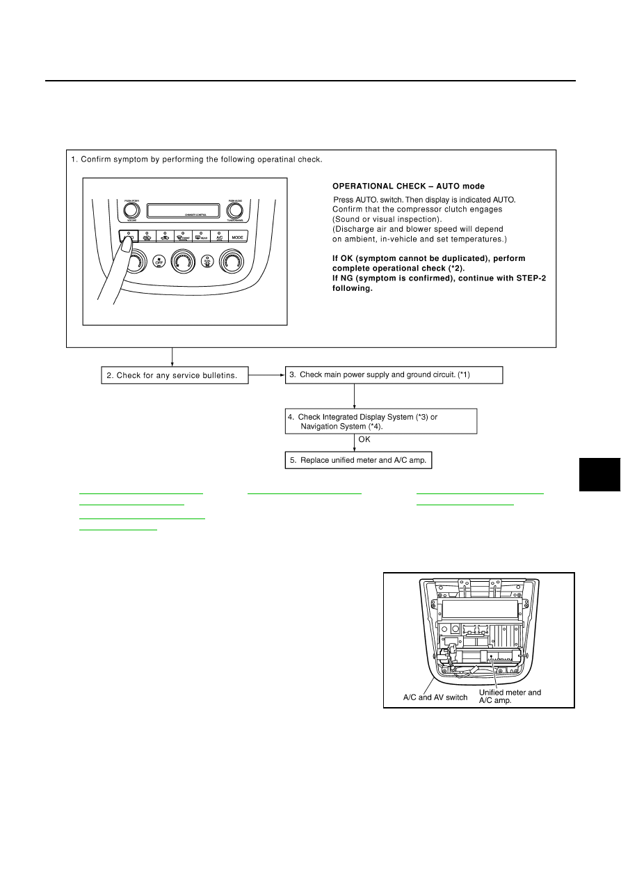
SYMPTOM: A/C system does not come on.
INSPECTION FLOW
COMPONENT DESCRIPTION
Unified Meter and A/C Amp. (Automatic Amplifier)
The unified meter and A/C amp. has a built-in microcomputer which
processes information sent from various sensors needed for air con-
ditioner operation. The air mix door motor, mode door motor, intake
door motor, blower motor and compressor are then controlled.
When the various switches and temperature control dials are oper-
ated, data is input to the unified meter and A/C amp. from the display
control unit using CAN communication.
Self-diagnosis functions are also built into unified meter and A/C
amp. to provide quick check of malfunctions in the auto air condi-
tioner system.
*1
ATC-58, "DIAGNOSIS PROCE-
DURE FOR A/C SYSTEM"
*2
*3
AV-121, "Example of Symptoms
Possible No Malfunction"
*4
AV-39, "A/C and AV Switch Self-
Diagnosis Function"
SJIA1158E
RJIA1758E