Nissan Murano Z50 (2005 year). Manual - part 223
TROUBLE DIAGNOSIS FOR SYMPTOMS
TF-41
C
E
F
G
H
I
J
K
L
M
A
B
TF
Revision: 2005 August
2005 Murano
3.
CHECK OUTPUT SIGNAL WITH UNIFIED METER AND A/C AMP.
With CONSULT-II
1.
Turn ignition switch “ON”. (Do not start engine.)
2.
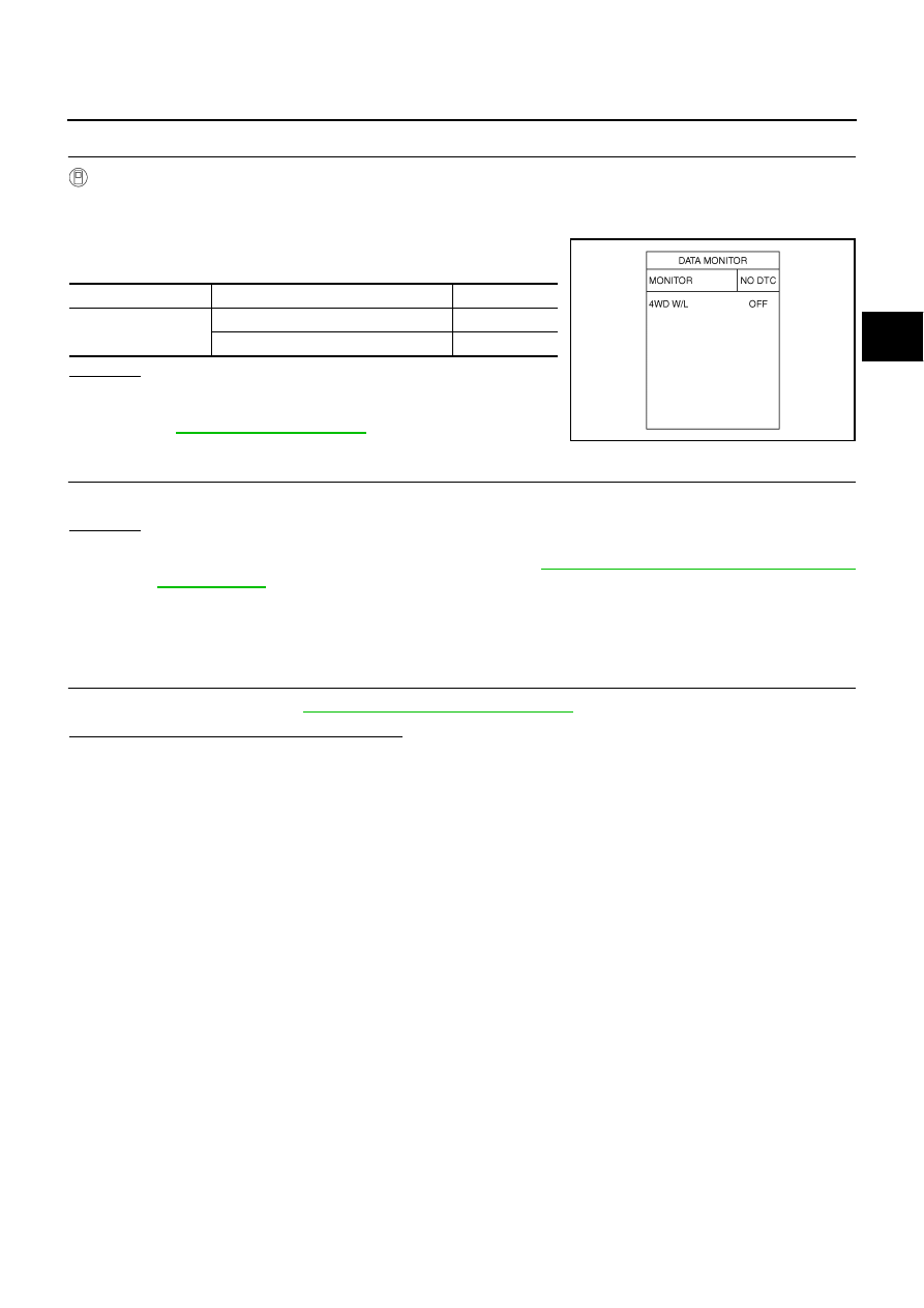
Select “DATA MONITOR” mode for “METER A/C AMP” with CONSULT-II.
3.
Start the engine, and then make sure that “4WD W/L” display
turns from “ON” to “OFF” after several seconds.
OK or NG
OK >> GO
TO
4.
NG
>> Perform trouble diagnosis for combination meter. Refer
to
.
4.
SYMPTOM CHECK
Check again.
OK or NG
OK
>> INSPECTION END
NG
>> Replace unified meter control unit assembly. Refer to
DI-26, "Disassembly and Assembly of Com-
AWD Warning Lamp Does Not Turn OFF Several Seconds after Engine Started
ADS000VS
DIAGNOSTIC PROCEDURE
1.
CHECK SELF-DIAGNOSTIC RESULTS
Perform self-diagnosis. Refer to
TF-25, "SELF-DIAG RESULT MODE"
Is any malfunction detected by self-diagnosis?
YES
>> Check the malfunctioning system.
NO
>> GO TO 2.
Monitor item
Condition
Display value
4WD W/L
Ignition switch ON
ON
Start engine (after several seconds)
OFF
SDIA2065E