Nissan Murano Z50 (2005 year). Manual - part 212
AUTOMATIC DRIVE POSITIONER
SE-33
C
D
E
F
G
H
J
K
L
M
A
B
SE
Revision: 2005 August
2005 Murano
Terminals and Reference Values for BCM
AIS003GI
Terminals and Reference Values for Driver Seat Control Unit
AIS003GJ
TERMINAL
WIRE
COLOR
ITEM
CONDITION
VOLTAGE (V)
(Approx)
11
P/B
Ignition switch ACC power supply
Ignition switch
(ACC or ON position)
Battery voltage
37
B/R
Key switch and key lock solenoid
Key switch ON (key is inserted in
ignition key cylinder)
Battery voltage
Key switch OFF (key is removed
from ignition key cylinder)
0
38
R
Ignition switch ON power supply
Ignition switch
(ON or START position)
Battery voltage
39
L
CAN-H
—
—
40
Y
CAN-L
—
—
42
GR
Power source (Fuse)
—
Battery voltage
52
B
Ground (Power)
—
0
55
W/B
Power source (Fusible link)
—
Battery voltage
62
SB
Drive side door switch
ON (Open)
→
OFF (Closed)
0
→
Battery voltage
TERMINAL
WIRE
COLOR
ITEM
CONDITION
VOLTAGE (V)
(Approx)
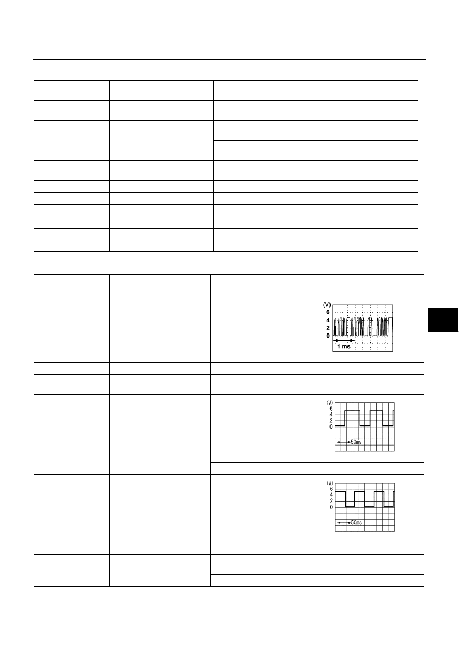
1
Y/W
UART LINE (RX)
Pedal adjusting switch ON (FR or
RR operation)
3
L/Y
CAN-H
—
—
6
Y/G
Ignition switch START power
supply
Ignition switch (START position)
Battery voltage
9
L
Reclining sensor signal
ON (seat reclining motor opera-
tion)
Other than above
0 or 5
10
W/R
Rear lifting sensor signal
ON (rear lifting motor operation)
Other than above
0 or 5
11
W/V
Sliding switch backward signal
ON (seat sliding switch backward
operation)
0
OFF
Battery voltage
PIIA4813E
SIIA0692J
SIIA0693J