Nissan Murano Z50 (2005 year). Manual - part 190


  Index      Manuals     Nissan Murano Z50 (2005 year) - Service and Repair Manual


Search            copyright infringement  


Content      ..     188      189      190      191     ..


Nissan Murano Z50 (2005 year). Manual - part 190


ENGINE OIL

LU-7

C

D

E

F

G

H

I

J

K

L

M

A

LU

Revision: 2005 August

2005 Murano

OIL PRESSURE CHECK

WARNING:

Be careful not to get burn yourself, as engine oil may be hot.

Oil pressure check should be done in “Parking position”.

1.

Check the engine oil level. Refer to 

LU-6, "ENGINE OIL LEVEL"

 .

2.

Remove splash guard (RH).

3.

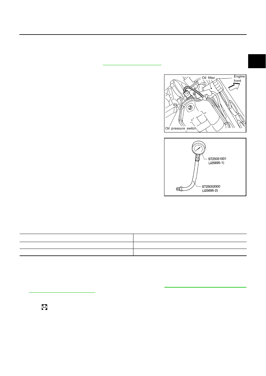
Disconnect harness connector at oil pressure switch, and
remove oil pressure switch using deep socket (commercial ser-
vice tool)

CAUTION:

Do not drop or shock oil pressure switch.

4.

Install pressure gauge [SST] and hose [SST].

5.

Start the engine and warm it up to normal operating temperature.

6.

Check the engine oil pressure with engine running under no-load.

NOTE:
When the engine oil temperature is low, the engine oil pressure becomes high.

Engine oil pressure [Engine oil temperature at 80

°

C (176

°

F)]

If difference is extreme, check engine oil passage and oil pump for engine oil leaks.

7.

After the inspections, install oil pressure switch as follows:

a.

Remove old liquid gasket adhering to oil pressure switch and mating surface.

b.

Apply liquid gasket and tighten oil pressure switch to the specification.
Use Genuine RTV Silicone Sealant or equivalent. Refer to 

GI-47, "RECOMMENDED CHEMICAL

PRODUCTS AND SEALANTS"

 .

SLC240B

SLC926

Engine speed (rpm)

Approximate discharge pressure [kPa (kg/cm

2

 , psi)]

Idle speed

More than 98 (1.0, 14)

2,000

More than 294 (3.0, 43)

Oil pressure switch:

: 14.8 N·m (1.5 kg-m, 11 ft-lb)

LU-8

ENGINE OIL

Revision: 2005 August

2005 Murano

Changing Engine Oil

ABS0035Q

WARNING:

Be careful not to get burn yourself, as engine oil may be hot.

Prolonged and repeated contact with used engine oil may cause skin cancer; try to avoid direct
skin contact with used engine oil. If skin contact is made, wash thoroughly with soap or hand
cleaner as soon as possible. 

1.

Warm up the engine, and check for engine oil leakage from engine components. Refer to 

LU-6, "ENGINE

OIL LEAKAGE"

 .

2.

Stop the engine and wait for 10 minutes.

3.

Loosen oil filler cap, and then remove drain plug.

4.

Drain engine oil.

5.

Install drain plug with new washer. Refer to 

EM-29, "OIL PAN AND OIL STRAINER"

 .

CAUTION:

Be sure to clean drain plug and install with new washer.

6.

Refill with new engine oil.
Engine oil specification and viscosity:
Refer to 

MA-10, "RECOMMENDED FLUIDS AND LUBRICANTS"

 .

Engine oil capacity (Approximate):

Unit: 

  (US qt, Imp qt)

CAUTION:

When filling engine oil, do not pull out oil level gauge.

The refill capacity depends on the engine oil temperature and drain time. Use these specifica-
tions for reference only.

Always use oil level gauge to determine the proper amount of engine oil in engine.

7.

Warm up engine and check area around drain plug and oil filter for engine oil leakage.

8.

Stop engine and wait for 10 minutes.

9.

Check the engine oil level. Refer to 

LU-6, "ENGINE OIL LEVEL"

 .

Oil pan drain plug:

 :34.3 N·m (3.5 kg-m, 25 ft-lb)

Drain and refill 

With oil filter change

4.5 (4-3/4, 4)

Without oil filter change

4.2 (4-1/2, 3-3/4)

Dry engine (Overhaul)

5.5 (5-3/4, 4-7/8)

OIL FILTER

LU-9

C

D

E

F

G

H

I

J

K

L

M

A

LU

Revision: 2005 August

2005 Murano

OIL FILTER

PFP:15208

Removal and Installation

ABS0035R

REMOVAL

1.

Remove splash guard (RH).

2.

Using oil filter wrench [SST], remove oil filter.

CAUTION:

Oil filter is provided with relief valve. Use Genuine Nissan
Oil Filter or equivalent.

Be careful not to get burned when engine and engine oil
may be hot.

When removing, prepare a shop cloth to absorb any
engine oil leakage or spillage.

Do not allow engine oil to adhere to drive belts.

Completely wipe off any engine oil that adheres to engine
and vehicle.

INSTALLATION

1.

Remove foreign materials adhering to oil filter installation surface.

2.

Apply engine oil to the oil seal contact surface of new oil filter.

3.

Screw oil filter manually until it touches the installation surface,
then tighten it by 2/3 turn. Or tighten to the specification.

INSPECTION AFTER INSTALLATION

1.

Check the engine oil level. Refer to 

LU-6, "ENGINE OIL"

 .

2.

Start engine, and check there is no leak of engine oil.

3.

Stop engine and wait for 10 minutes.

4.

Check the engine oil level and adjust the level. Refer to 

LU-6, "ENGINE OIL"

 .

SMA039D

SMA010

Oil filter:

 : 17.6 N·m (1.8 kg-m, 13 ft-lb)

SMA229B

LU-10

OIL COOLER

Revision: 2005 August

2005 Murano

OIL COOLER

PFP:21305

Removal and Installation

ABS0035S

WARNING:

Be careful not to get burn yourself, as engine oil and engine coolant may be hot.

REMOVAL

NOTE:
When remove oil cooler only, step 2 is unnecessary.

1.

Remove splash guard (RH).

2.

Drain engine coolant from radiator and cylinder block. Refer to 

CO-9, "Changing Engine Coolant"

  and

EM-114, "DISASSEMBLY"

 .

NOTE:
Perform this step when removing water pipes.

3.

Remove oil filter. Refer to 

LU-9, "OIL FILTER"

 .

CAUTION:

Do not spill engine oil on drive belt.

4.

Disconnect water hoses from oil cooler.

When removing oil cooler only, pinching water hoses near oil cooler to prevent engine coolant from
spilling out.

Remaining engine coolant in piping will come out. Use a tray to collect it.

1.

Connector bolt

2.

Copper gasket

3.

Water drain plug

4.

Water pipe

5.

Bracket

6.

Water hose

7.

Relief valve

8.

O-ring

9.

Oil cooler

10.

Connector bolt

11.

Oil filter

12. Water hose

13.

Water pipe

14. Clamp

15. Water hose

16.

Clamp

PBIC4166E

OIL COOLER

LU-11

C

D

E

F

G

H

I

J

K

L

M

A

LU

Revision: 2005 August

2005 Murano

CAUTION:

Perform this step when the engine is cold.

Do not spill engine coolant on drive belts.

5.

Remove connector bolt, and remove oil cooler.

CAUTION:

Do not spill engine oil to rubber parts such as drive belts and engine mounting insulator.

6.

Remove water pipes, as necessary.

INSPECTION AFTER REMOVAL
Oil Cooler

Check oil cooler for cracks. Check oil cooler for clogging by blowing through engine coolant inlet. If necessary,
replace oil cooler.

Relief Valve

Inspect relief valve for movement, cracks and breaks by pushing the ball. If replacement is necessary, remove
relief valve by prying it out with a suitable tool. Install a new relief valve in place by tapping it.

INSTALLATION

Note the following, and install in the reverse order of removal.

Make sure that no foreign objects are adhering to the installation surfaces of oil cooler and oil pan (upper).

Align cutout on oil cooler with protrusion on oil pan (upper) side,
and tighten connector bolt.

INSPECTION AFTER INSTALLATION

1.

Check the engine oil level and the engine coolant level and add engine oil and engine coolant. Refer to

LU-6, "ENGINE OIL"

 an

CO-9, "ENGINE COOLANT"

 .

2.

Start the engine, and check there is no leaks of engine oil or engine coolant.

3.

Stop the engine and wait for 10 minutes.

4.

Check the engine oil level and the engine coolant level again. Refer to 

LU-6, "ENGINE OIL"

 an

CO-9,

"ENGINE COOLANT"

 .

PBIC2508E

LU-12

OIL PUMP

Revision: 2005 August

2005 Murano

OIL PUMP

PFP:15010

Removal and Installation

ABS0035T

REMOVAL

1.

Remove oil pans (lower and upper) and oil strainer. Refer to 

EM-29, "OIL PAN AND OIL STRAINER"

 .

2.

Remove front timing chain case and timing chain (primary). Refer to 

EM-60, "TIMING CHAIN"

 .

3.

Remove oil pump assembly.

INSTALLATION

CAUTION:

Before installation, apply new engine oil to the parts as instructed in the figure.
Note the following, and install in the reverse order of removal.

When installing, align crankshaft flat faces with oil pump inner rotor flat faces.

INSPECTION AFTER INSTALLATION

1.

Check the engine oil level. Refer to 

LU-6, "ENGINE OIL"

 .

2.

Start the engine, and check there is no leaks of engine oil.

3.

Stop the engine and wait for 10 minutes.

4.

Check the engine oil level and adjust engine oil. Refer to 

LU-6, "ENGINE OIL"

 .

Disassembly and Assembly

ABS0035U

DISASSEMBLY

1.

Remove oil pump cover.

2.

Remove oil pump inner rotor and oil pump outer rotor from oil pump body.

3.

After removing regulator valve plug, remove regulator valve spring and regulator valve.

1.

Oil pump body

2.

Oil pump outer rotor

3.

Oil pump inner rotor

4.

Oil pump cover

5.

Regulator valve plug

6.

Regulator valve spring

7.

Regulator valve

PBIC2691E

OIL PUMP

LU-13

C

D

E

F

G

H

I

J

K

L

M

A

LU

Revision: 2005 August

2005 Murano

INSPECTION AFTER DISASSEMBLY
Oil Pump Clearance

Measure the clearance with feeler gauge.

Clearance between oil pump outer rotor and oil pump body
(position “1”)

Tip clearance between oil pump inner rotor and oil pump outer
rotor (position “2”)

Measure the clearance with feeler gauge and straightedge.

Side clearance between oil pump inner rotor and oil pump body
(position “3”)

Side clearance between oil pump outer rotor and oil pump body
(position “4”)

Calculate the clearance between oil pump inner rotor and oil pump body as follows:

OIL PUMP BODY INNER DIAMETER

Measure the inner diameter of oil pump body with inside
micrometer. (Position “5”)

OIL PUMP INNER ROTOR OUTER DIAMETER

Measure the outer diameter of protruded portion of oil pump
inner rotor with micrometer. (Position “6”)

OIL PUMP INNER ROTOR TO OIL PUMP BODY CLEARANCE

(Clearance) = (Oil pump body inner diameter) – (Oil pump inner rotor outer diameter)

If measured/calculated values are out of the standard, replace oil pump assembly.

Standard

: 0.114 - 0.260 mm (0.0045 - 0.0102 in)

Standard

: Below 0.180 mm (0.0071 in)

SLC932A

Standard

: 0.030 - 0.070 mm (0.0012 - 0.0028 in)

Standard

: 0.050 - 0.110 mm (0.0020 - 0.0043 in)

SLC933A

PBIC0821E

Standard

: 0.045 - 0.091 mm (0.0018 - 0.0036 in)

LU-14

OIL PUMP

Revision: 2005 August

2005 Murano

Regulator Valve Clearance

(Clearance) = (Valve hole diameter) – (Regulator valve outer diame-
ter)

If the calculated value is out of the standard, replace oil pump
assembly.

CAUTION:

Coat regulator valve with engine oil.

Make sure that it falls smoothly into valve hole by its own
weight.

ASSEMBLY

Note the following, and assemble in the reverse order of disassemble.

Install oil pump inner rotor with the groove faced to oil pump
cover side.

Standard

: 0.040 - 0.097 mm (0.0016 - 0.0038 in)

PBIC0822E

PBIC0832E

SERVICE DATA AND SPECIFICATIONS (SDS)

LU-15

C

D

E

F

G

H

I

J

K

L

M

A

LU

Revision: 2005 August

2005 Murano

SERVICE DATA AND SPECIFICATIONS (SDS)

PFP:00030

Standard and Limit

ABS004RF

OIL PRESSURE

*: Engine oil temperature at 80

°

C (176

°

F)

ENGINE OIL CAPACITY (APPROXIMATE)

Unit: 

 (US qt, Imp qt)

OIL PUMP

Unit: mm (in)

REGULATOR VALVE

Unit: mm (in)

Engine speed (rpm)

Approximate discharge pressure* [kPa (kg/cm

2

 , psi)] 

Idle speed

More than 98 (1.0, 14)

2,000

More than 294 (3.0, 43) 

Drain and refill

With oil filter change

4.5 (4-3/4, 4)

Without oil filter change

4.2 (4-1/2, 3-3/4)

Dry engine (Overhaul)

5.5 (5-3/4, 4-7/8)               

Oil pump body to oil pump outer rotor radial clearance

0.114 - 0.260 (0.0045 - 0.0102)

Oil pump inner rotor to oil pump outer rotor tip clearance

Below 0.180 (0.0071)

Oil pump body to oil pump inner rotor side clearance

0.030 - 0.070 (0.0012 - 0.0028)

Oil pump body to oil pump outer rotor side clearance

0.050 - 0.110 (0.0020 - 0.0043)

Oil pump inner rotor to oil pump body clearance

0.045 - 0.091 (0.0018 - 0.0036)

Regulator valve to oil pump body clearance

0.040 - 0.097 (0.0016 - 0.0038)

LU-16

SERVICE DATA AND SPECIFICATIONS (SDS)

Revision: 2005 August

2005 Murano

MA-1

MAINTENANCE

L  MAINTENANCE

CONTENTS

C

D

E

F

G

H

I

J

K

M

SECTION 

MA

A

B

MA

Revision: 2005 August

2005 Murano

MAINTENANCE

PREPARATION ........................................................... 3

Special Service Tools  ............................................... 3
Commercial Service Tools ........................................ 3

GENERAL MAINTENANCE  ....................................... 4

Explanation of General Maintenance  ....................... 4

PERIODIC MAINTENANCE  ....................................... 6

Introduction of Periodic Maintenance  ....................... 6
Schedule 1  ............................................................... 7

EMISSION CONTROL SYSTEM MAINTE-
NANCE .................................................................. 7
CHASSIS AND BODY MAINTENANCE  ............... 8

Schedule 2  ............................................................... 8

EMISSION CONTROL SYSTEM MAINTE-
NANCE .................................................................. 8
CHASSIS AND BODY MAINTENANCE  ............... 9

RECOMMENDED FLUIDS AND LUBRICANTS  ...... 10

Fluids and Lubricants  ............................................. 10
SAE Viscosity Number  ............................................11

GASOLINE ENGINE OIL  .....................................11

Anti-Freeze Coolant Mixture Ratio  ..........................11

ENGINE MAINTENANCE  ......................................... 12

Checking Drive Belts  .............................................. 12
Tension Adjustment ................................................ 12

ALTERNATOR AND A/C COMPRESSOR BELT 

... 13

POWER STEERING OIL PUMP BELT  ............... 13

Changing Engine Coolant  ...................................... 13

DRAINING ENGINE COOLANT  ......................... 14
REFILLING ENGINE COOLANT  ........................ 14
FLUSHING COOLING SYSTEM ......................... 15

Checking Fuel Lines ............................................... 16
Changing Air Cleaner Filter .................................... 16

VISCOUS PAPER TYPE ..................................... 16

Changing Engine Oil  .............................................. 17
Changing Oil Filter  ................................................. 17

REMOVAL ........................................................... 17
INSTALLATION ................................................... 18
INSPECTION AFTER INSTALLATION  ............... 18

Changing Spark Plugs (Platinum-Tipped Type)  ..... 18

REMOVAL ........................................................... 18
INSPECTION AFTER REMOVAL  ....................... 19

INSTALLATION ................................................... 19

Checking EVAP Vapor Lines  .................................. 19

CHASSIS AND BODY MAINTENANCE  ................... 20

Checking Exhaust System ...................................... 20
Checking CVT Fluid ................................................ 20

FLUID LEVEL CHECK  ........................................ 20
FLUID CONDITION CHECK  ............................... 21

Changing CVT Fluid  ............................................... 21
Checking Transfer Oil  ............................................. 21
Changing Transfer Oil  ............................................ 22
Checking Propeller Shaft ........................................ 22
Checking Differential Gear Oil  ................................ 22
Changing Differential Gear Oil ................................ 23
Balancing Wheels (Bonding Weight Type)  ............. 23

REMOVAL ........................................................... 23
WHEEL BALANCE ADJUSTMENT ..................... 23

Tire Rotation  ........................................................... 24
Checking Brake Fluid Level and Leaks  .................. 25
Checking Brake Lines and Cables  ......................... 25
Changing Brake Fluid  ............................................. 25
Checking Disc Brake  .............................................. 25

ROTOR ................................................................ 25
CALIPER ............................................................. 26
PAD ..................................................................... 26

Checking Steering Gear and Linkage ..................... 26

STEERING GEAR  ............................................... 26
STEERING LINKAGE  ......................................... 26

Checking Power Steering Fluid and Lines .............. 26
Axle and Suspension Parts  .................................... 27
Drive Shaft .............................................................. 27
Lubricating Locks, Hinges and Hood Latch  ............ 28
Checking Seat Belt, Buckles, Retractors, Anchors 
and Adjusters .......................................................... 29

SERVICE DATA AND SPECIFICATIONS (SDS)  ...... 30

Standard and Limit .................................................. 30

BELT DEFLECTION AND TENSION  .................. 30
ENGINE COOLANT CAPACITY (APPROXI-
MATE) .................................................................. 30
RADIATOR .......................................................... 30
ENGINE OIL CAPACITY (APPROXIMATE)  ........ 30

PREPARATION

MA-3

C

D

E

F

G

H

I

J

K

M

A

B

MA

Revision: 2005 August

2005 Murano

PREPARATION

PFP:00002

Special Service Tools

ALS00097

The actual shapes of Kent-Moore tools may differ from those of special service tools illustrated here.

Commercial Service Tools

ALS0008M

Tool number
(Kent-Moore No.)
Tool name

Description

KV10115801
(J38956)
Oil filter wrench

Removing and installing oil filter
a: 64.3 mm (2.531 in)

S-NT375

(Kent-Moore No.)
Tool name

Description

(

)

Power tool

Loosening nuts and bolts

(

)

Spark plug wrench

Removing and installing spark plug

(BT3373-F)
Belt tension gauge

Checking drive belt tension

PBIC0190E

S-NT047

AMA126

MA-4

GENERAL MAINTENANCE

Revision: 2005 August

2005 Murano

GENERAL MAINTENANCE

PFP:00000

Explanation of General Maintenance

ALS000D7

General maintenance includes those items which should be checked during the normal day-to-day operation
of the vehicle. They are essential if the vehicle is to continue operating properly. The owners can perform
checks and inspections themselves or have their NISSAN dealers do them.

OUTSIDE THE VEHICLE

The maintenance items listed here should be performed from time to time, unless otherwise specified.

INSIDE THE VEHICLE

The maintenance items listed here should be checked on a regular basis, such as when performing periodic maintenance, cleaning the
vehicle, etc.

Item

Reference page

Tires

Check the pressure with a gauge, including the spare, at least once a month 
and always prior to a long distance trips. Adjust to the specified pressure if nec-
essary. Check carefully for damage, cuts or excessive wear.

Wheel nuts

When checking the tires, make sure no nuts are missing, and check for any 
loose nuts. Tighten if necessary.

Windshield

Clean the windshield on a regular basis. Check the windshield at least every six 
months for cracks or other damage. Repair as necessary.

Tire rotation

Tires should be rotated every 12,000 km (7,500 miles).

MA-24

Wheel alignment and 
balance

If the vehicle pulls to either side while driving on a straight and level road, or if 
you detect uneven or abnormal tire wear, there may be a need for wheel align-
ment. If the steering wheel or seat vibrates at normal highway speeds, wheel 
balancing may be needed.

MA-23

FSU-5


Windshield wiper 
blades

Check for cracks or wear if they do not wipe properly.

Doors and engine 
hood

Check that all doors and the engine hood operate smoothly as well as the trunk 
lid and back hatch. Also make sure that all latches lock securely. Lubricate if 
necessary. Make sure that the secondary latch keeps the hood from opening 
when the primary latch is released.
When driving in areas using road salt or other corrosive materials, check lubri-
cation frequently.

MA-28

Lamps

Make sure that the headlamps, stop lamps, tail lamps, turn signal lamps, and 
other lamps are all operating properly and installed securely. Also check head-
lamp aim. Clean the headlamps on a regular basis. 

Item

Reference page

Warning lamps and 
chimes

Make sure that all warning lamps and chimes are operating properly.

Windshield wiper and 
washer

Check that the wipers and washer operate properly and that the wipers do not 
streak.

Windshield defroster

Check that the air comes out of the defroster outlets properly and in sufficient 
quantity when operating the heater or air conditioner.

Steering wheel

Check that it has the specified play. Be sure to check for changes in the steering 
condition, such as excessive play, hard steering or strange noises.
 Free play: Less than 35 mm (1.38 in)

Seats

Check seat position controls such as seat adjusters, seatback recliner, etc. to 
make sure they operate smoothly and that all latches lock securely in every 
position. Check that the head restrains move up and down smoothly and that 
the locks (if equipped) hold securely in all latched positions. Check that the 
latches lock securely for folding-down rear seatbacks.

Seat belts

Check that all parts of the seat belt system (e.g. buckles, anchors, adjusters and 
retractors) operate properly and smoothly, and are installed securely. Check the 
belt webbing for cuts, fraying, wear or damage.

MA-29

Accelerator pedal

Check the pedal for smooth operation and make sure the pedal does not catch 
or require uneven effort. Keep the floor mats away from the pedal.

Brakes

Check that the brake does not pull the vehicle to one side when applied.

GENERAL MAINTENANCE

MA-5

C

D

E

F

G

H

I

J

K

M

A

B

MA

Revision: 2005 August

2005 Murano

UNDER THE HOOD AND VEHICLE

The maintenance items listed here should be checked periodically (e.g. each time you check the engine oil or refuel).

Brake pedal and 
booster

Check the pedal for smooth operation and make sure it has the proper distance 
under it when depressed fully. Check the brake booster function. Be sure to 
keep the floor mats away from the pedal.

BR-6

BR-22


Parking brake

Check that the pedal has the proper travel and make sure that the vehicle is 
held securely on a fairly steep hill when only the parking brake is applied.

PB-2

CVT P (Park) position 
mechanism

On a fairly steep hill check that the vehicle is held securely with the selector 
lever in the P (Park) position without applying any brakes.

Item

Reference page

Item

Reference page

Windshield washer 
fluid

Check that there is adequate fluid in the tank.

Engine coolant level

Check the coolant level when the engine is cold.

MA-13

Radiator and hoses

Check the front of the radiator and clean off any dirt, insects, leaves, etc., that 
may have accumulated. Make sure the hoses have no cracks, deformation, 
deterioration or loose connections.

Brake fluid level

Make sure that the brake fluid level is between the “MAX” and “MIN” lines on the 
reservoir.

MA-25

Battery

Check the fluid level in each cell. It should be between the “MAX” and “MIN” 
lines. Vehicles operated in high temperatures or under severe conditions require 
frequent checks of the battery fluid level.

Engine drive belts

Make sure that no belt is frayed, worn, cracked or oily.

MA-12

Engine oil level

Check the level on the oil level gauge after parking the vehicle on a level spot 
and turning off the engine.

MA-17

Power steering fluid 
level and lines

Check the level on the dipstick with the engine off. Check the lines for improper 
attachment, leaks, cracks, etc.

MA-26

Exhaust system

Make sure there are no loose supports, cracks or holes. If the sound of the 
exhaust seems unusual or there is a smell of exhaust fumes, immediately locate 
the trouble and correct it.

MA-20

Underbody

The underbody is frequently exposed to corrosive substances such as those 
used on icy roads or to control dust. It is very important to remove these sub-
stances, otherwise rust will form on the floor pan, frame, fuel lines and around 
the exhaust system. At the end of winter, the underbody should be thoroughly 
flushed with plain water, being careful to clean those areas where mud and dirt 
can easily accumulate.

Fluid leaks

Check under the vehicle for fuel, oil, water or other fluid leaks after the vehicle 
has been parked for a while. Water dripping from the air conditioner after use is 
normal. If you should notice any leaks or gasoline fumes are evident, check for 
the cause and correct it immediately.

MA-6

PERIODIC MAINTENANCE

Revision: 2005 August

2005 Murano

PERIODIC MAINTENANCE

PFP:00026

Introduction of Periodic Maintenance

ALS000D8

Two different maintenance schedules are provided, and should be used, depending upon the conditions in
which the vehicle is mainly operated. After 60,000 miles (96,000 km) or 48 months, continue the periodic
maintenance at the same mileage/time intervals.

Schedule 1

Follow Periodic Maintenance Schedule 1 if the driving habits frequently include 
one or more of the following driving conditions:

Repeated short trips of less than 5 miles (8 km).

Repeated short trips of less than 10 miles (16 km) with outside temperatures 
remaining below freezing.

Operating in hot weather in stop-and-go “rush hour” traffic.

Extensive idling and/or low speed driving for long distances, such as police, 
taxi or door-to-door delivery use.

Driving in dusty conditions.

Driving on rough, muddy, or salt spread roads.

Towing a trailer, using a camper or a car-top carrier.

Emission Control Sys-
tem Maintenance

MA-7

Chassis and Body 
Maintenance

MA-8

Schedule 2

Follow Periodic Maintenance Schedule 2 if none of driving conditions shown in 
Schedule 1 apply to the driving habits.

Emission Control Sys-
tem Maintenance

MA-8

Chassis and Body 
Maintenance

MA-9


Content      ..     188      189      190      191     ..