Nissan Murano Z50 (2005 year). Manual - part 189
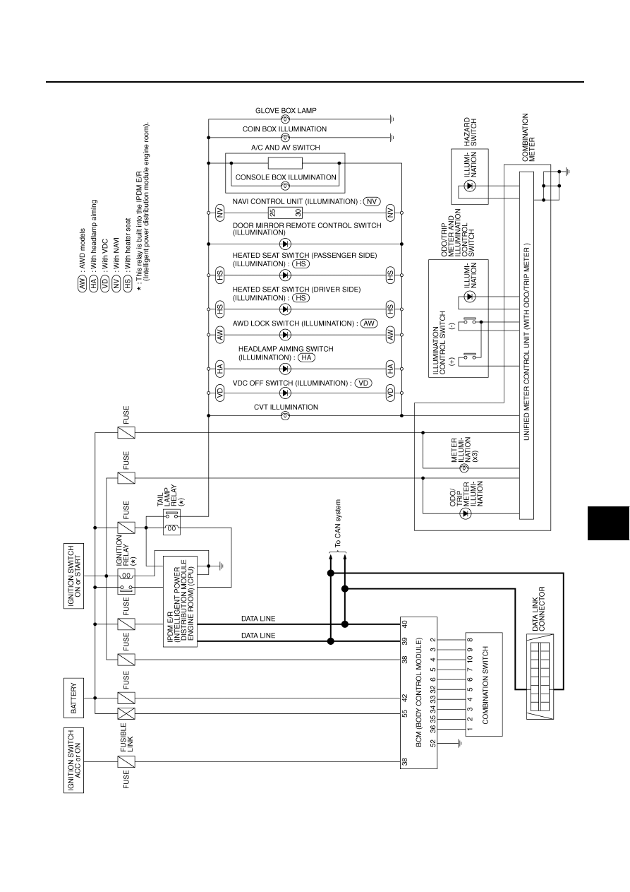
ILLUMINATION
LT-211
C
D
E
F
G
H
I
J
L
M
A
B
LT
Revision: 2005 August
2005 Murano
Schematic
AKS004MJ
TKWB0476E
|
|
|
ILLUMINATION LT-211 C D E F G H I J L M A B LT Revision: 2005 August 2005 Murano Schematic AKS004MJ TKWB0476E |