Nissan Murano Z50 (2005 year). Manual - part 183
FRONT FOG LAMP
LT-115
C
D
E
F
G
H
I
J
L
M
A
B
LT
Revision: 2005 August
2005 Murano
Terminals and Reference Values for IPDM E/R
AKS00AM4
How to Proceed With Trouble Diagnosis
AKS00AM5
1.
Confirm the symptom or customer complaint.
2.
Understand operation description and function description. Refer to
3.
Perform the preliminary check. Refer to
4.
Check symptom and repair or replace the cause of malfunction.
5.
Does the front fog lamp operate normally? If YES, GO TO 6. If NO, GO TO 4.
6.
INSPECTION END
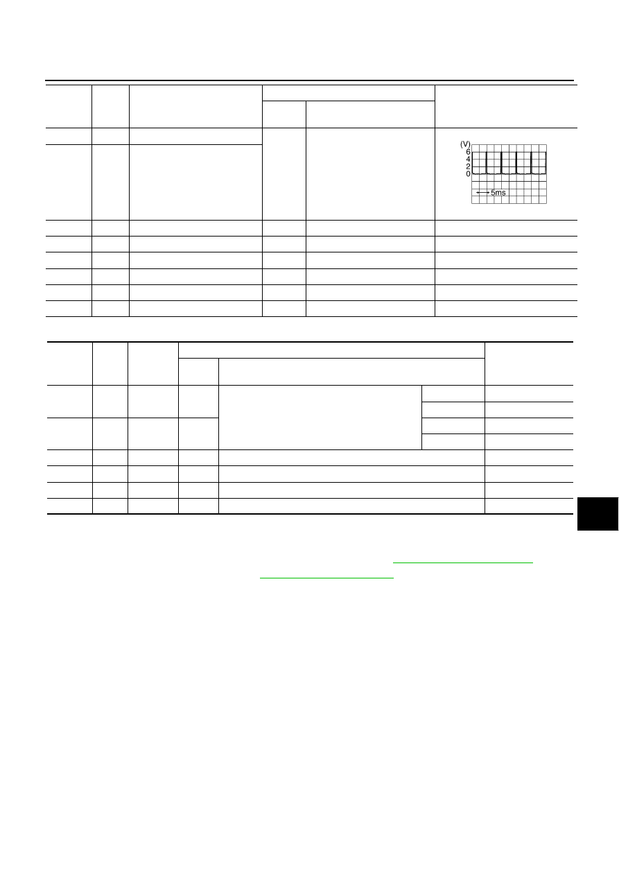
35
G/B
Combination switch output 2
ON
Lighting, turn, wiper OFF
Wiper dial position 4
36
L/W
Combination switch output 1
38
R
Ignition switch (ON)
ON
—
Battery voltage
39
L
CAN
−
H
—
—
—
40
Y
CAN
−
L
—
—
—
42
GR
Battery power supply
OFF
—
Battery voltage
52
B
Ground
ON
—
Approx. 0V
55
W/B
Battery power supply
OFF
—
Battery voltage
Terminal
No.
Wire
color
Signal name
Measuring condition
Reference value
Ignition
switch
Operation or condition
SKIA5292E
Terminal
No.
Wire
color
Signal
name
Measuring condition
Reference value
Ignition
switch
Operation or condition
36
G/W
Front fog
lamp (RH)
ON
Lighting switch must be in the 2ND position or
AUTO position (headlamp is ON) and the front fog
lamp switch must be ON.
OFF
Approx. 0V
ON
Battery voltage
37
W/R
Front fog
lamp (LH)
ON
OFF
Approx. 0V
ON
Battery voltage
38
B
Ground
ON
—
Approx. 0V
48
L
CAN
−
H
—
—
—
49
Y
CAN
−
L
—
—
—
60
B
Ground
ON
—
Approx. 0V