Nissan Murano Z50 (2005 year). Manual - part 179
HEADLAMP -CONVENTIONAL TYPE-
LT-51
C
D
E
F
G
H
I
J
L
M
A
B
LT
Revision: 2005 August
2005 Murano
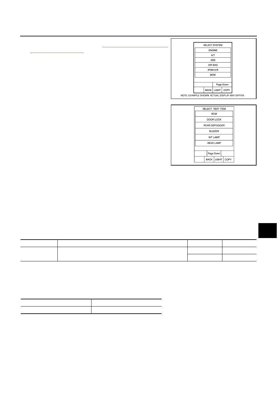
3.
Touch “BCM” on “SELECT SYSTEM” screen.
If “BCM” is not indicated, refer to
.
4.
Touch “HEAD LAMP” on “SELECT TEST ITEM” screen.
WORK SUPPORT
Operation Procedure
1.
Touch “HEAD LAMP” on “SELECT TEST ITEM” screen.
2.
Touch “WORK SUPPORT” on “SELECT DIAG MODE” screen.
3.
Touch item on “SELECT WORK ITEM” screen.
4.
Touch “START”.
5.
Touch “CHANGE SET”.
6.
The setting will be changed and “CUSTOMIZING COMPLETED” will be displayed.
7.
Touch “END”.
Display Item List
DATA MONITOR
Operation Procedure
1.
Touch “HEAD LAMP” on “SELECT TEST ITEM” screen.
2.
Touch “DATA MONITOR” on “SELECT DIAG MODE” screen.
3.
Touch either “ALL SIGNALS” or “SELECTION FROM MENU” on “SELECT MONITOR ITEM” screen.
4.
When “SELECTION FROM MENU” is selected, touch individual items to be monitored. When “ALL SIG-
NALS” is selected, all the items will be monitored.
5.
Touch “START”.
6.
Touch “RECORD” while monitoring, then the status of the monitored item can be recorded. To stop
recording, touch “STOP”.
BCIA0030E
PKIA5226E
Item
Description
CONSULT-II
Factory setting
BATTERY SAVER
SET
Exterior lamp battery saver control mode can be changed in this mode.
Selects exterior lamp battery saver control mode between two ON/OFF.
ON
×
OFF
—
ALL SIGNALS
Monitors all the signals.
SELECTION FROM MENU
Selects items and monitors them.