Nissan Murano Z50 (2005 year). Manual - part 145


  Index      Manuals     Nissan Murano Z50 (2005 year) - Service and Repair Manual


Search            copyright infringement  


Content      ..     143      144      145      146     ..


Nissan Murano Z50 (2005 year). Manual - part 145


GW-62

POWER WINDOW SYSTEM

Revision: 2005 August

2005 Murano

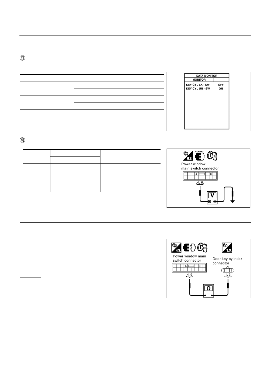
Door Key Cylinder Switch Check/With Intelligent Key 

AIS006A1

1. 

CHECK DOOR KEY CYLINDER SWITCH INPUT SIGNAL

 With CONSULT-II

Check door key cylinder switch (“KEY CYL LK-SW”, “KEY CYL UN-SW”) in “DATA MONITOR” mode with
CONSULT-II.

 Without CONSULT-II

Check voltage between power window main switch connector and ground.

OK or NG

OK

>> Door key cylinder switch is OK.

NG

>> GO TO 2.

2. 

CHECK DOOR KEY CYLINDER SWITCH CIRCUIT

1.

Turn ignition switch OFF.

2.

Disconnect power window main switch and door key cylinder switch connector.

3.

Check continuity between power window main switch connector
D6 terminal 4, 6 and door key cylinder switch connector D11 ter-
minals 1, 3.

OK or NG

OK

>> GO TO 3.

NG

>> Repair or replace harness.

Monitor item

Condition

KEY CYL LK- SW

Lock: ON

Neutral/Unlock: OFF

KEY CYL UN- SW

Unlock: ON

Neutral/Lock: OFF

PIIA6285E

Connector

Terminals (Wire color)

Key position 

Voltage (V) 

(Approx.)

(+)

(–)

D6

4 (L)

Ground

Lock

0

Neutral/Unlock

5

6 (R)

Unlock

0

Neutral/Lock

5

PIIA4211E

4 (L) – 1 (L)

: Continuity should exist.

6 (R) – 3 (R)

: Continuity should exist.

PIIB4367E

POWER WINDOW SYSTEM

GW-63

C

D

E

F

G

H

J

K

L

M

A

B

GW

Revision: 2005 August

2005 Murano

3. 

CHECK DOOR KEY CYLINDER SWITCH GROUND 

Check continuity between door key cylinder switch connector D11
terminal 2 and ground.

OK or NG

OK

>> GO TO 4.

NG

>> Repair or replace harness.

4. 

CHECK DOOR KEY CYLINDER SWITCH

Check continuity between door key cylinder switch connector D11 terminals 1, 3 and 2.

OK or NG

OK

>> GO TO 5.

NG

>> Replace door key cylinder switch.

5. 

CHECK POWER WINDOW MAIN SWITCH OUTPUT SIGNAL

1.

Connect power window main switch connector.

2.

Check voltage between power window main switch connector
D6 terminal 4. 6 and ground.

OK or NG

OK

>> Check the condition of the harness and the connector.

NG

>> Replace power window main switch.

2 (B) – Ground

: Continuity should exist.

PIIA3354E

Connector

Terminal

Key position

Continuity 

D11

1

2

Neutral/Unlock

No

Lock

Yes

3

Neutral/Lock

No

Unlock

Yes

PIIA3355E

4 (L) – Ground

: Approx. 5V

6 (R) – Ground

: Approx. 5V

PIIA4211E

GW-64

POWER WINDOW SYSTEM

Revision: 2005 August

2005 Murano

Power Window Serial Link Check

AIS002DR

1. 

CHECK POWER WINDOW SWITCH OUTPUT SIGNAL

 With CONSULT-II

Check door lock and unlock switch (“LOCK SW DR/AS”, “UNLK SW DR/AS”) in DATA MONITOR mode with
CONSULT-II. Refer to 

GW-38, "DATA MONITOR"

 Without CONSULT-II

1.

Remove key from ignition switch, and the door of driver side and passenger side is closed.

2.

Check the signal between BCM connector and ground with oscilloscope when door lock and unlock
switch (driver side and passenger side) is turned “LOCK” or “UNLOCK”.

3.

Make sure signals which are shown in the figure below can be detected during 10 second just after door
lock and unlock switch (driver side and passenger side) is turned “LOCK” or “UNLOCK”.

OK or NG

OK

>> GO TO 2.

NG

>> GO TO 3.

2. 

CHECK BCM OUTPUT SIGNAL

Check power window serial link (“POWER WINDOW DOWN”) in “ACTIVE TEST” mode with CONSULT-II.
Refer to 

GW-38, "ACTIVE TEST"

OK or NG

OK

>> Power window serial link is OK.

NG

>> Replace BCM.

Monitor item

Condition

LOCK SW DR / AS

LOCK

: ON

UNLOCK

: OFF

UNLK SW DR / AS

LOCK

: ON

UNLOCK

: OFF

PIIA6289E

Connector

Terminals (Wire color)

Signal

(Reference value)

(+)

(–)

M34

22 (BR/W)

Ground

PIIA6290E

PIIA1297E

When “ACTIVE TEST” is executed, is the window of 
driver and passenger side lowered.

PIIA3080E

POWER WINDOW SYSTEM

GW-65

C

D

E

F

G

H

J

K

L

M

A

B

GW

Revision: 2005 August

2005 Murano

3. 

CHECK POWER WINDOW SWITCH GROUND 

1.

Turn ignition switch OFF.

2.

Disconnect power window main switch and front power window switch (passenger side) connector.

3.

Check continuity between power window main switch connector
D7 terminal 17 and ground.

4.

Check continuity between front power window switch (passen-
ger side) connector D35 terminal 11 and ground.

OK or NG

OK

>> GO TO 4.

NG

>> Repair or replace harness.

4. 

CHECK POWER WINDOW SERIAL LINK CIRCUIT

1.

Disconnect BCM connector.

2.

Check continuity between BCM connector M34 terminal 22 and
power window main switch connector D6 terminal 14.

3.

Check continuity between BCM connector M34 terminal 22 and
front power window switch (passenger side) connector D35 ter-
minal 16.

OK or NG

OK

>> Replace power window main switch.

NG

>> Repair or replace harness.

17 (B) – Ground

: Continuity should exist.

PIIA4172E

11 (B) – Ground

: Continuity should exist.

PIIA4175E

22 (BR/W) – 14 (BR/W)

: Continuity should exist.

PIIA6291E

22 (BR/W) – 16 (BR/W)

: Continuity should exist.

PIIA6292E

GW-66

POWER WINDOW SYSTEM

Revision: 2005 August

2005 Murano

Power Window Lock Switch Check 

AIS002EM

1. 

CHECK POWER WINDOW MAIN SWITCH 

Exchanges for a normal power window main switch, and operation is checked.

OK or NG

OK

>> Replace malfunction power window main switch.

NG

>> Check the condition of the harness and the connector.

Does power window lock operate?

FRONT DOOR GLASS AND REGULATOR

GW-67

C

D

E

F

G

H

J

K

L

M

A

B

GW

Revision: 2005 August

2005 Murano

FRONT DOOR GLASS AND REGULATOR

PFP:80300

Removal and Installation

AIS001SF

DOOR GLASS
Removal

1.

Remove the front door finisher. Refer to 

EI-30, "DOOR FINISHER"

 .

2.

Operate the power window main switch to raise/lower the door
window until the glass mounting bolts can be seen.

3.

Remove the glass mounting bolts.

1.    Door glass

2.

Regulator assembly

3.

Power window  motor

4.

Module assembly

PIIA3786E

PIIA3789E

GW-68

FRONT DOOR GLASS AND REGULATOR

Revision: 2005 August

2005 Murano

4.

While holding the door glass, raise it at the rear end to pull the
glass out of the sash toward the outside of the door.

Installation

Install in the reverse order of removal.

REGULATOR ASSEMBLY
Removal

1.

Remove the front door finisher. Refer to 

EI-30, "DOOR FINISHER"

 .

2.

Operate the power window main switch to raise/lower the door
window until the glass mounting bolts can be seen.

3.

Remove the glass mounting bolts.

4.

Raise up the door glass and hold with a suction lifter.

5.

Remove the mounting bolts, and remove the module assembly.

6.

Disconnect the harness connector for the module assembly, and
unclip the harness from the back.

Installation

Install in the reverse order of removal.

PIIA4004E

PIIA3789E

PIIB1811E

SIIA0287E

FRONT DOOR GLASS AND REGULATOR

GW-69

C

D

E

F

G

H

J

K

L

M

A

B

GW

Revision: 2005 August

2005 Murano

Inspection after Removal

Check the regulator assembly for the following items. If a malfunc-
tion is detected, replace or grease it.

Wire wear

Regulator deformation

Grease condition for each sliding part

The arrows in the figure show the application points of the multi-pur-
pose grease.

Disassembly and Assembly

AIS0068N

REGULATOR ASSEMBLY
Disassembly

Remove  power window motor and guide rail from  module assem-
bly.

Assembly

Assemble in the reverse order of removal.

Inspection after Installation

AIS006FC

SETTING OF LIMIT SWITCH

If any of the following work has been done, reset the limit switch (integrated in the motor).

Removal and installation of the regulator.

Removal and installation of the motor from the regulator.

Operate the regulators as a unit.

Removal and installation of the glass.

Removal and installation of the glass run.

Resetting

After installing each component to the vehicle, follow the steps below.
1.

Remove the motor from regulator.

2.

Connect the connector. Rotate the motor unit with power window switch for more than 5 sec in glass rais-
ing direction.

3.

Install motor to regulator.

4.

Raise glass to the top position.

CAUTION:

Do not use Auto switch to raise the glass to the top position.

FITTING INSPECTION

Make sure the glass is securely fit into the glass run groove.

Lower the glass slightly [approx. 10 to 20 mm (0.39 to 0.79 in)] and make sure the clearance to the sash is
parallel. If the clearance between the glass and sash is not parallel, loosen the regulator mounting bolts,
guide rail mounting bolts, and glass and guide rail mounting bolts to correct the glass position.

PIIA3787E

PIIA3788E

GW-70

REAR DOOR GLASS AND REGULATOR

Revision: 2005 August

2005 Murano

REAR DOOR GLASS AND REGULATOR

PFP:82300

Removal and Installation

AIS001SG

DOOR GLASS
Removal

1.

Remove the rear door finisher. Refer to 

EI-30, "DOOR FINISHER"

 .

2.

Remove the rear door outside molding. Refer to 

EI-23, "DOOR OUTSIDE MOLDING"

 .

3.

Remove the sealing screen.

4.

Remove the rear lower sash.

5.

Operate the power window switch to raise/lower the door win-
dow until the glass mounting bolts can be seen.

6.

Remove the glass mounting bolts, and remove the glass from
the inside of the panel.

Installation

Install in the reverse order of removal.

REGULATOR ASSEMBLY
Removal

1.

Remove the rear door finisher. Refer to 

EI-30, "DOOR FINISHER"

 .

2.

Remove the rear door outside molding. Refer to 

EI-23, "DOOR OUTSIDE MOLDING"

 .

1.

Door glass

2.

Regulator assembly

3.

Power window motor

PIIA3790E

PIIA3791E

REAR DOOR GLASS AND REGULATOR

GW-71

C

D

E

F

G

H

J

K

L

M

A

B

GW

Revision: 2005 August

2005 Murano

3.

Remove the sealing screen.

4.

Remove the rear lower sash.

5.

Operate the power window switch to raise/lower the door win-
dow until the glass mounting bolts can be seen.

6.

Remove the glass mounting bolts.

7.

Raise up the door glass and hold with a suction lifter.

8.

Remove the regulator mounting bolts, and remove the regulator
from the panel.

9.

Disconnect the connector for the regulator assembly.

Installation

Install in the reverse order of removal.

Inspection after Removal

Check the regulator assembly for the following items. If a malfunction is detected, replace or grease it.

Wire wear

Regulator deformation

Grease condition for each sliding part

The arrows in the figure show the application points of the multi-pur-
pose grease.

PIIA3791E

PIIB1817E

PIIA3792E

PIIA6327J

GW-72

REAR DOOR GLASS AND REGULATOR

Revision: 2005 August

2005 Murano

Disassembly and Assembly

AIS0068P

REGULATOR ASSEMBLY
Disassembly

Remove  power window motor from regulator assembly.

Assembly

Assemble in the reverse order of removal.

Inspection after Installation

AIS0068Q

FITTING INSPECTION

Make sure the glass is securely fit into the glass run groove.

Lower the glass slightly [approx. 10 to 20 mm (0.39 to 0.79 in)], and make sure the clearance to the sash
is parallel. If the clearance between the glass and sash is not parallel, loosen the regulator mounting bolts,
guide rail mounting bolts, and glass and carrier plate mounting bolts to correct the glass position.

INSIDE MIRROR

GW-73

C

D

E

F

G

H

J

K

L

M

A

B

GW

Revision: 2005 August

2005 Murano

INSIDE MIRROR

PFP:96321

Wiring Diagram –I/MIRR–

AIS001SH

TIWA0440E

GW-74

INSIDE MIRROR

Revision: 2005 August

2005 Murano

Removal and Installation

AIS001SI

CAUTION:

Apply Genuine Mirror Adhesive or equivalent to bonding surface of mounting bracket. Refer to 

GI-47,

"RECOMMENDED CHEMICAL PRODUCTS AND SEALANTS"

 .

REMOVAL

1.

Remove inside mirror finisher (if equipped).

2.

Remove screw of mirror base.

3.

Slide the mirror upward to remove.

4.

Disconnect the connector (if equipped).

INSTALLATION

Install in the reverse order of removal.

1.

Inside mirror

2.

Inside mirror finisher (if equipped)

PIIA9845E

REAR WINDOW DEFOGGER

GW-75

C

D

E

F

G

H

J

K

L

M

A

B

GW

Revision: 2005 August

2005 Murano

REAR WINDOW DEFOGGER

PFP:25350

Component Parts and Harness Connector Location

AIS002IB

System Description

AIS002IC

The rear window defogger system is controlled by BCM (Body Control Module) and IPDM E/R (Intelligent
Power Distribution Module Engine Room). 
The rear window defogger  operates only for approximately 15 minutes. 
Power is at all times supplied

through 20A fuse [No. 75, and 80, located in the IPDM E/R] 

to rear window defogger relay terminals  3 and  6.

through 15A fuse [No. 38, located in the fuse block (J/B)]

to A/C and AV switch terminal 1.

through 50A fusible link [letter F , located in the fuse block (J/B)]

PIIA9682E

GW-76

REAR WINDOW DEFOGGER

Revision: 2005 August

2005 Murano

to BCM terminal 55.

through 10A fuse [No.18, located in the fuse block (J/B)]

to BCM terminal 42.

With the ignition switch turned to ON or START position, 
Power is supplied

through 10A fuse [No.12, located in the fuse block (J/B)]

to rear window defogger relay terminal 1.

through 10A fuse [No.1, located in the fuse block (J/B)]

to BCM terminal 38.

through 10A fuse [No. 6, located in the fuse block (J/B)]

to A/C and AV switch terminal 2.

Ground is supplied 

to BCM terminal 52

through body grounds E13, E26 and E28.

to A/C and AV switch terminal 5

through body grounds M14 and M78.

to internal CPU of IPDM E/R terminals 38 and 60

through body grounds E13, E26 and E28. 

When A/C and AV switch (rear window defogger switch) is turned to ON,  
Ground is supplied 

to BCM terminal 9

through A/C and AV switch terminal 16 

through A/C and AV switch terminal 5

through body grounds M14 and M78.

Then rear window defogger switch is illuminated.
Then BCM recognizes that rear window defogger switch is turned to ON. 
Then it sends rear window defogger switch signals to IPDM E/R and display control unit (with navigation) or
display unit (without navigation) via DATA LINE (CAN H, CAN L).
When display control unit (with navigation) or display unit (without navigation) receives rear window defogger
switch signals, and display on the screen.
When IPDM E/R receives rear window defogger switch signals, 
Ground is supplied

to rear window defogger relay terminal 2,

through IPDM E/R terminal 52,

through internal CPU of IPDM E/R and IPDM E/R terminal 60.

through body grounds E13, E26 and E28, 

and then rear window defogger relay is energized. 
When rear window defogger relay is turned ON, 
Power is transmitted,

through rear window defogger relay terminals 5 and 7

to rear window defogger terminal 1,

Rear window defogger terminal 2, is grounded through body grounds  B7 and B20. 

With power and ground supplied, rear window defogger filaments heat and defog the rear window.
When rear window defogger relay is turned to ON, (with door mirror defogger)
Power is supplied

through rear window defogger relay terminals 5 and 7,

through fuse block (J/B) terminal 2C,

through 10A fuse [No. 8, located in the fuse block (J/B)],

through fuse block (J/B) terminal 5B.

to door mirror defogger (Driver side and passenger side) terminal 6.

Door mirror defogger (Driver side and passenger side) terminal 5 is grounded through body grounds M14 and
M78.

REAR WINDOW DEFOGGER

GW-77

C

D

E

F

G

H

J

K

L

M

A

B

GW

Revision: 2005 August

2005 Murano

With power and ground supplied, rear window defogger filaments heat and defog the rear window and door
mirror defogger filaments heat and defog the mirror. 


Content      ..     143      144      145      146     ..