Nissan Murano Z50 (2005 year). Manual - part 134
EXHAUST SYSTEM
EX-3
C
D
E
F
G
H
I
J
K
L
M
A
EX
Revision: 2005 August
2005 Murano
EXHAUST SYSTEM
PFP:20100
Checking Exhaust System
ABS0033U
Check exhaust pipes, muffler and mounting for improper attachment,
leaks, cracks, damage or deterioration.
●
If anything found, repair or replace damage parts.
Removal and Installation
ABS0033V
CAUTION:
●
Be sure to use genuine exhaust system parts or equivalents which are specially designed for heat
resistance, corrosion resistance, and shape.
●
Perform the operation with the exhaust system fully cooled down because the system will be hot
just after engine stops.
●
Be careful not to cut your hand on heat insulator edge.
REMOVAL
Disconnect each joint and mounting using power tool.
SMA211A
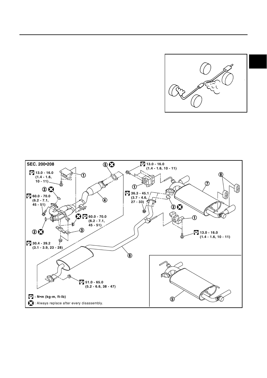
1.
Mounting bracket
2.
Ring gasket
3.
Exhaust front tube bracket
4.
Exhaust front tube
5.
Gasket
6.
Center muffler
7.
Main muffler
8.
Mounting rubber
9.
Main muffler (GXE grade)
PBIC1777E