Nissan Murano Z50 (2005 year). Manual - part 129
TIMING CHAIN
EM-77
C
D
E
F
G
H
I
J
K
L
M
A
EM
Revision: 2005 August
2005 Murano
b.
Apply a continuous bead of liquid gasket with the tube presser
[SST: WS39930000 (
—
)] to intake valve timing control cov-
ers as shown in the figure.
Use Genuine RTV Silicone Sealant or equivalent. Refer to
GI-47, "RECOMMENDED CHEMICAL PRODUCTS AND
SEALANTS"
.
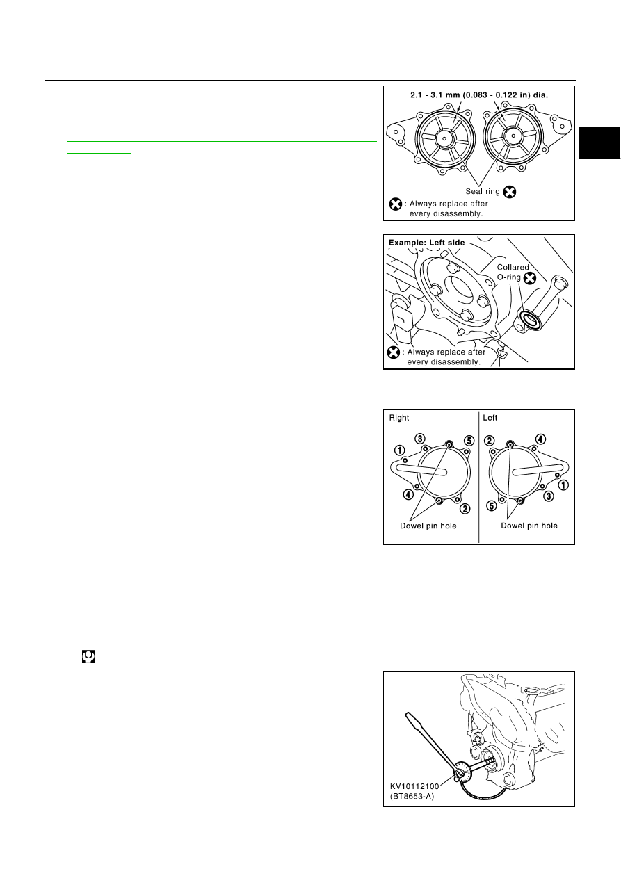
c.
Install new collared O-rings in front timing chain case oil hole
(left and right sides).
d.
Being careful not to move seal rings from the installation grooves, align dowel pins on front timing chain
case with the holes to install intake valve timing control covers.
e.
Tighten mounting bolts in numerical order as shown in the fig-
ure.
16. Install crankshaft pulley as follows:
a.
Install crankshaft pulley, taking care not to damage front oil seal.
●
When press-fitting crankshaft pulley with a plastic hammer, tap on its center portion (not circumfer-
ence).
b.
Fix crankshaft with the pulley holder [SST: KV10109300 (
—
)].
c.
Tighten crankshaft pulley bolt.
d.
Turn crankshaft pulley bolt 90 degrees clockwise (angle tighten-
ing).
CAUTION:
Check the tightening angle by using the angle wrench
[SST]. Avoid judgement by visual inspection without SST.
●
Check tightening angle indicated on the angle wrench indica-
tor plate.
SBIA0492E
PBIC2631E
PBIC0918E
: 44.1 N·m (4.5 kg-m, 33 ft-lb)
PBIC4224E