Nissan Murano Z50 (2005 year). Manual - part 121


  Index      Manuals     Nissan Murano Z50 (2005 year) - Service and Repair Manual


Search            copyright infringement  


Content      ..     119      120      121      122     ..


Nissan Murano Z50 (2005 year). Manual - part 121


ASCD BRAKE SWITCH

EC-691

C

D

E

F

G

H

I

J

K

L

M

A

EC

Revision: 2005 August

2005 Murano

2. 

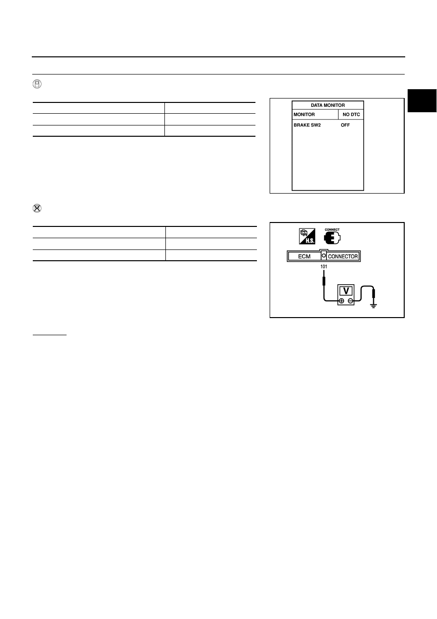
CHECK OVERALL FUNCTION-II

 With CONSULT-II

Check “BRAKE SW2” indication in “DATA MONITOR” mode. 

 Without CONSULT-II

Check voltage between ECM terminal 101 and ground under the following conditions.

OK or NG

OK

>> INSPECTION END

NG

>> GO TO 8.

CONDITION

INDICATION

Brake pedal: Fully released

OFF

Brake pedal: Slightly depressed

ON

SEC013D

CONDITION

VOLTAGE

Brake pedal: Fully released

Approximately 0V

Brake pedal: Slightly depressed

Battery voltage

MBIB0060E

EC-692

ASCD BRAKE SWITCH

Revision: 2005 August

2005 Murano

3. 

CHECK ASCD BRAKE SWITCH POWER SUPPLY CIRCUIT

1.

Turn ignition switch OFF.

2.

Disconnect ASCD brake switch harness connector.

3.

Turn ignition switch ON.

4.

Check voltage between ASCD brake switch terminal 1 and
ground with CONSULT-II or tester.

OK or NG

OK

>> GO TO 5.

NG

>> GO TO 4.

4. 

DETECT MALFUNCTIONING PART

Check the following.

Fuse block (J/B) connector E101

10A fuse

Harness for open or short between ASCD brake switch and fuse

>> Repair open circuit or short to ground or short to power in harness or connectors.

5. 

CHECK ASCD BRAKE SWITCH INPUT SIGNAL CIRCUIT FOR OPEN AND SHORT

1.

Turn ignition switch OFF.

2.

Disconnect ECM harness connector.

3.

Check harness continuity between ECM terminal 108 and ASCD brake switch terminal 2.
Refer to Wiring Diagram.

4.

Also check harness for short to ground and short to power.

OK or NG

OK

>> GO TO 7.

NG

>> GO TO 6.

6. 

DETECT MALFUNCTIONING PART

Check the following.

Harness connectors E109, M6

Harness for open or short between ECM and ASCD brake switch

>> Repair open circuit or short to ground or short to power in harness or connectors.

PBIB1368E

Voltage: Battery voltage

PBIB0857E

Continuity should exist.

ASCD BRAKE SWITCH

EC-693

C

D

E

F

G

H

I

J

K

L

M

A

EC

Revision: 2005 August

2005 Murano

7. 

CHECK ASCD BRAKE SWITCH

Refer to 

EC-591, "Component Inspection"

 .

OK or NG

OK

>> GO TO 13.

NG

>> Replace ASCD brake switch.

8. 

CHECK STOP LAMP SWITCH POWER SUPPLY CIRCUIT

1.

Turn ignition switch OFF.

2.

Disconnect stop lamp switch harness connector.

3.

Check voltage between stop lamp switch terminal 1 and ground
with CONSULT -II or tester.

OK or NG

OK

>> GO TO 10.

NG

>> GO TO 9.

9. 

DETECT MALFUNCTIONING PART

Check the following.

Fuse block (J/B) connector E101

10A fuse

Harness for open or short between stop lamp switch and fuse

>> Repair open circuit or short to ground or short to power in harness or connectors.

10. 

CHECK STOP LAMP SWITCH INPUT SIGNAL CIRCUIT FOR OPEN AND SHORT

1.

Disconnect ECM harness connector.

2.

Check harness continuity between ECM terminal 101 and stop lamp switch terminal 2.
Refer to Wiring Diagram.

3.

Also check harness for short to ground and short to power.

OK or NG

OK

>> GO TO 12.

NG

>> GO TO 11.

PBIB1368E

Voltage: Battery voltage

PBIB0117E

Continuity should exist.

EC-694

ASCD BRAKE SWITCH

Revision: 2005 August

2005 Murano

11. 

DETECT MALFUNCTIONING PART

Check the following.

Harness connectors E110, M7

Harness for open or short between ECM and stop lamp switch

>> Repair open circuit or short to ground or short to power in harness or connectors.

12. 

CHECK STOP LAMP SWITCH

Refer to 

EC-591, "Component Inspection"

 .

OK or NG

OK

>> GO TO 13.

NG

>> Replace stop lamp switch.

13. 

CHECK INTERMITTENT INCIDENT

Refer to 

EC-157, "TROUBLE DIAGNOSIS FOR INTERMITTENT INCIDENT"

 .

>> INSPECTION END

Component Inspection

ABS004P5

ASCD BRAKE SWITCH

1.

Turn ignition switch OFF.

2.

Disconnect ASCD brake switch harness connector.

3.

Check continuity between ASCD brake switch terminals 1 and 2
under the following conditions.

If NG, adjust ASCD brake switch installation, refer to 

BR-6,

"BRAKE PEDAL"

 , and perform step 3 again.

STOP LAMP SWITCH

1.

Turn ignition switch OFF.

2.

Disconnect stop lamp switch harness connector.

3.

Check continuity between stop lamp switch terminals 1 and 2
under the following conditions.

If NG, adjust stop lamp switch installation, refer to 

BR-6,

"BRAKE PEDAL"

 , and perform step 3 again.

Condition

Continuity

Brake pedal: Fully released

Should exist

Brake pedal: Slightly depressed

Should not exist

SEC023D

Condition

Continuity

Brake pedal: Fully released

Should not exist

Brake pedal: Slightly depressed

Should exist

PBIB0118E

ASCD INDICATOR

EC-695

C

D

E

F

G

H

I

J

K

L

M

A

EC

Revision: 2005 August

2005 Murano

ASCD INDICATOR

PFP:24814

Component Description

ABS004P6

ASCD indicator lamp illuminates to indicate ASCD operation status. Lamp has two indicators, CRUISE and
SET, and is integrated in combination meter.
CRUISE indicator illuminates when MAIN switch on ASCD steering switch is turned ON to indicated that
ASCD system is ready for operation.
SET indicator illuminates when following conditions are met. 

CRUISE indicator is illuminated.

SET/COAST switch on ASCD steering switch is turned ON while vehicle speed is within the range of
ASCD setting.

SET indicator remains lit during ASCD control.
Refer to 

EC-28, "AUTOMATIC SPEED CONTROL DEVICE (ASCD)"

   for the ASCD function.

CONSULT-II Reference Value in Data Monitor Mode

ABS004VV

Specification data are reference value.

MONITOR ITEM

CONDITION

SPECIFICATION

CRUISE LAMP

Ignition switch: ON

MAIN switch: Pressed at the 1st time 

 at the 2nd time

ON 

 OFF

SET LAMP

MAIN switch: ON

When vehicle speed is between 
40 km/h (25 MPH) and 144 km/h 
(89 MPH)

ASCD: Operating

ON

ASCD: Not operating

OFF

EC-696

ASCD INDICATOR

Revision: 2005 August

2005 Murano

Wiring Diagram

ABS004VW

TBWA0394E

ASCD INDICATOR

EC-697

C

D

E

F

G

H

I

J

K

L

M

A

EC

Revision: 2005 August

2005 Murano

Diagnostic Procedure

ABS004VX

1. 

CHECK OVERALL FUNCTION

Check ASCD indicator under the following conditions.

OK or NG

OK

>> INSPECTION END

NG

>> GO TO 2.

2. 

CHECK DTC

Check that DTC U1000 or U1001 is not displayed.

OK or NG

OK

>> GO TO 3.

NG

>> Perform trouble diagnoses for DTC U1000, U1001. Refer to 

EC-167, "DTC U1000, U1001 CAN

COMMUNICATION LINE"

 .

3. 

CHECK DTC WITH “UNIFIED METER AND A/C AMP.”

Refer to 

DI-32, "SELF-DIAGNOSTIC RESULTS"

 .

OK or NG

OK

>> GO TO 4.

NG

>> Go to 

DI-31, "CONSULT-II Function (METER A/C AMP)"

 .

4. 

CHECK INTERMITTENT INCIDENT

Refer to 

EC-157, "TROUBLE DIAGNOSIS FOR INTERMITTENT INCIDENT"

 .

>> INSPECTION END

MONITOR ITEM

CONDITION

SPECIFICATION

CRUISE LAMP

Ignition switch: ON

MAIN switch: Pressed at the 1st time 

 at the 2nd time

ON 

 OFF

SET LAMP

MAIN switch: ON

When vehicle speed is between 
40 km/h (25 MPH) and 144 km/h 
(89 MPH)

ASCD: Operating

ON

ASCD: Not operating

OFF

EC-698

MIL AND DATA LINK CONNECTOR

Revision: 2005 August

2005 Murano

MIL AND DATA LINK CONNECTOR

PFP:24814

Wiring Diagram

ABS004PA

TBWA0374E

MIL AND DATA LINK CONNECTOR

EC-699

C

D

E

F

G

H

I

J

K

L

M

A

EC

Revision: 2005 August

2005 Murano

TBWB0356E

EC-700

SERVICE DATA AND SPECIFICATIONS (SDS)

Revision: 2005 August

2005 Murano

SERVICE DATA AND SPECIFICATIONS (SDS)

PFP:00030

Fuel Pressure

ABS004PM

Idle Speed and Ignition Timing

ABS004PN

*: Under the following conditions:

Air conditioner switch: OFF

Electric load: OFF (Lights, heater fan & rear window defogger)

Steering wheel: Kept in straight-ahead position

Calculated Load Value

ABS004PO

Mass Air Flow Sensor

ABS004PP

*: Engine is warmed up to normal operating temperature and running under no-load.

Intake Air Temperature Sensor

ABS004PQ

Engine Coolant Temperature Sensor

ABS004PR

Air Fuel Ratio (A/F) Sensor 1 Heater

ABS004PS

Heated Oxygen Sensor 2 Heater

ABS004PT

Crankshaft Position Sensor (POS)

ABS004PU

Refer to 

EC-303, "Component Inspection"

  .

Camshaft Position Sensor (PHASE)

ABS004PV

Refer to 

EC-312, "Component Inspection"

  .

Throttle Control Motor

ABS004PW

Fuel pressure at idling kPa (kg/cm

2

  , psi)

Approximately 350 (3.57, 51)

Target idle speed

No-load*  (in P or N position)

650

±

50 rpm

Air conditioner: ON

In P or N position

700 rpm or more

Ignition timing

In P or N position

15

°


±

 5

°

 BTDC

Calculated load value % (Using CONSULT-II or GST)

At idle

5 - 35

At 2,500 rpm

5 - 35

Supply voltage

Battery voltage (11 - 14V)

Output voltage at idle

1.0 - 1.2*V

Mass air flow (Using CONSULT-II or GST)

2.0 - 6.0 g·m/sec at idle*

7.0 - 20.0 g·m/sec at 2,500 rpm*

Temperature 

°

C (

°

F)

Resistance k

25 (77)

1.800 - 2.200

80 (176)

0.283 - 0.359

Temperature 

°

C (

°

F)

Resistance k

20 (68)

2.1 - 2.9

50 (122)

0.68 - 1.00

90 (194)

0.236 - 0.260

Resistance [at 25

°

C (77

°

F)]

2.3 - 4.3

Resistance [at 25

°

C (77

°

F)]

5.0 - 7.0

Resistance [at 25

°

C (77

°

F)]

Approximately 1 - 15

SERVICE DATA AND SPECIFICATIONS (SDS)

EC-701

C

D

E

F

G

H

I

J

K

L

M

A

EC

Revision: 2005 August

2005 Murano

Injector

ABS004PX

Fuel Pump

ABS004PY

Resistance [at 10 - 60

°

C (50 -140

°

F)]

11.1 - 14.5

Resistance [at 25

°

C (77

°

F)]

Approximately 0.2 - 5.0

EC-702

SERVICE DATA AND SPECIFICATIONS (SDS)

Revision: 2005 August

2005 Murano

EI-1

EXTERIOR & INTERIOR

I  BODY

CONTENTS

C

D

E

F

G

H

J

K

L

M

SECTION 

EI

A

B

EI

Revision: 2005 August

2005 Murano

EXTERIOR & INTERIOR

PRECAUTIONS .......................................................... 3

Precautions for Supplemental Restraint System 
(SRS) “AIR BAG” and “SEAT BELT PRE-TEN-
SIONER” .................................................................. 3
Precautions for Work ................................................ 3

PREPARATION ........................................................... 4

Special Service Tools  ............................................... 4
Commercial Service Tools ........................................ 4

SQUEAK AND RATTLE TROUBLE DIAGNOSES ..... 5

Work Flow  ................................................................ 5

CUSTOMER INTERVIEW ..................................... 5
DUPLICATE THE NOISE AND TEST DRIVE  ....... 6
CHECK RELATED SERVICE BULLETINS  ........... 6
LOCATE THE NOISE AND IDENTIFY THE 
ROOT CAUSE  ...................................................... 6
REPAIR THE CAUSE  ........................................... 6
CONFIRM THE REPAIR  ....................................... 7

Generic Squeak and Rattle Troubleshooting  ........... 7

INSTRUMENT PANEL  .......................................... 7
CENTER CONSOLE ............................................. 7
DOORS ................................................................. 7
TRUNK .................................................................. 8
SUNROOF/HEADLINING ..................................... 8
SEATS ................................................................... 8
UNDERHOOD ....................................................... 8

Diagnostic Worksheet  .............................................. 9

CLIP AND FASTENER  ..............................................11

Clip and Fastener ....................................................11

FRONT BUMPER  ..................................................... 14

Removal and Installation  ........................................ 14

REMOVAL ........................................................... 16
INSTALLATION ................................................... 16

REAR BUMPER  ....................................................... 17

Removal and Installation  ........................................ 17

REMOVAL ........................................................... 19
INSTALLATION ................................................... 19
REAR BUMPER CLOSING ................................. 19
DRAFTER GUARD  ............................................. 19

FRONT GRILLE  ........................................................ 20

Removal and Installation  ........................................ 20

REMOVAL ........................................................... 20
INSTALLATION ................................................... 20

COWL TOP  ............................................................... 21

Removal and Installation  ........................................ 21

REMOVAL ........................................................... 21
INSTALLATION ................................................... 21

FENDER PROTECTOR  ............................................ 22

Removal and Installation  ........................................ 22

REMOVAL ........................................................... 22
INSTALLATION ................................................... 22

DOOR OUTSIDE MOLDING  ..................................... 23

Removal and Installation  ........................................ 23

FRONT DOOR OUTSIDE MOLDING .................. 23
REAR DOOR OUTSIDE MOLDING  .................... 23

DOOR OUTSIDE LOWER MOLDING  ...................... 24

Removal and Installation  ........................................ 24

FRONT DOOR OUTSIDE LOWER MOLDING ... 24
REAR DOOR OUTSIDE LOWER MOLDING ...... 24
FRONT FENDER LOWER MOLDING  ................ 24

DOOR PARTING SEAL  ............................................ 25

Removal and Installation  ........................................ 25

REMOVAL ........................................................... 25
INSTALLATION ................................................... 25

WINDSHIELD MOLDING  .......................................... 26

Removal and Installation  ........................................ 26

WINDSHIELD MOLDING  .................................... 26

SIDE WINDOW GLASS  ............................................ 27

Removal and Installation  ........................................ 27

SIDE WINDOW MOLDING  ................................. 27

ROOF SIDE MOLDING ............................................. 28

Removal and Installation  ........................................ 28

REMOVAL ........................................................... 28
INSTALLATION ................................................... 28

ROOF RAIL  ............................................................... 29

Removal and Installation  ........................................ 29

REMOVAL ........................................................... 29
INSTALLATION ................................................... 29

EI-2

Revision: 2005 August

2005 Murano

DOOR FINISHER  ...................................................... 30

Removal and Installation  ........................................ 30

DOOR FINISHER (FRONT AND REAR) ............. 30

BODY SIDE TRIM  ..................................................... 32

Removal and Installation  ........................................ 32

CENTER PILLAR LOWER GARNISH  ................. 32
CENTER PILLAR UPPER GARNISH .................. 32
DASH SIDE FINISHER  ....................................... 33
FRONT PILLAR GARNISH  ................................. 33
FRONT AND REAR KICKING PLATE ................. 33
FRONT AND REAR BODY SIDE WELT  ............. 33

FLOOR TRIM  ............................................................ 34

Removal and Installation  ........................................ 34

REMOVAL ........................................................... 34
INSTALLATION .................................................... 35

HEADLINING .............................................................36

Removal and Installation .........................................36

REMOVAL ............................................................37
INSTALLATION ....................................................37

LUGGAGE FLOOR TRIM  .........................................38

Removal and Installation .........................................38

REMOVAL ............................................................39
INSTALLATION ....................................................39

BACK DOOR TRIM  ...................................................40

Removal and Installation .........................................40

REMOVAL ............................................................40
INSTALLATION ....................................................40

PRECAUTIONS

EI-3

C

D

E

F

G

H

J

K

L

M

A

B

EI

Revision: 2005 August

2005 Murano

PRECAUTIONS

PFP:00001

Precautions for Supplemental Restraint System (SRS) “AIR BAG” and “SEAT 
BELT PRE-TENSIONER”

AIS005DB

The Supplemental Restraint System such as “AIR BAG” and “SEAT BELT PRE-TENSIONER”, used along
with a front seat belt, helps to reduce the risk or severity of injury to the driver and front passenger for certain
types of collision. This system includes seat belt switch inputs and dual stage front air bag modules. The SRS
system uses the seat belt switches to determine the front air bag deployment, and may only deploy one front
air bag, depending on the severity of a collision and whether the front occupants are belted or unbelted.
Information necessary to service the system safely is included in the SRS and SB section of this Service Man-
ual.

WARNING:

To avoid rendering the SRS inoperative, which could increase the risk of personal injury or death
in the event of a collision which would result in air bag inflation, all maintenance must be per-
formed by an authorized NISSAN/INFINITI dealer.

Improper maintenance, including incorrect removal and installation of the SRS, can lead to per-
sonal injury caused by unintentional activation of the system. For removal of Spiral Cable and Air
Bag Module, see the SRS section.

Do not use electrical test equipment on any circuit related to the SRS unless instructed to in this
Service Manual. SRS wiring harnesses can be identified by yellow and/or orange harnesses or
harness connectors.

Precautions for Work

AIS005DC

After removing and installing the opening/closing parts, be sure to carry out fitting adjustments to check
their operation.

Check the lubrication level, damage, and wear of each part. If necessary, grease or replace it.

EI-4

PREPARATION

Revision: 2005 August

2005 Murano

PREPARATION

PFP:00002

Special Service Tools

AIS005DD

The actual shapes of Kent-Moore tools may differ from those of special service tools illustrated here.

Commercial Service Tools

AIS005DE

Tool number
(Kent-Moore No.)
Tool name

Description

(J-39570)
Chassis ear

Locating the noise

(J-43980)
NISSAN Squeak and Rattle 
Kit

Repairing the cause of noise

SIIA0993E

SIIA0994E

Tool name

Description

Engine ear

Locating the noise

SIIA0995E


Content      ..     119      120      121      122     ..