Nissan Murano Z50 (2005 year). Manual - part 117
DTC P2135 TP SENSOR
EC-627
C
D
E
F
G
H
I
J
K
L
M
A
EC
Revision: 2005 August
2005 Murano
DTC P2135 TP SENSOR
PFP:16119
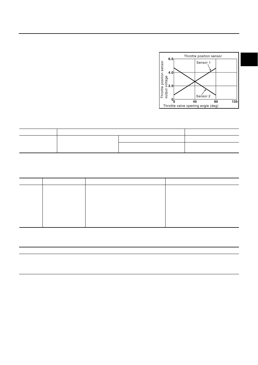
Component Description
ABS004NT
Electric throttle control actuator consists of throttle control motor,
throttle position sensor, etc. The throttle position sensor responds to
the throttle valve movement.
The throttle position sensor has the two sensors. These sensors are
a kind of potentiometers which transform the throttle valve position
into output voltage, and emit the voltage signal to the ECM. In addi-
tion, these sensors detect the opening and closing speed of the
throttle valve and feed the voltage signals to the ECM. The ECM
judges the current opening angle of the throttle valve from these sig-
nals and the ECM controls the throttle control motor to make the
throttle valve opening angle properly in response to driving condi-
tion.
CONSULT-II Reference Value in Data Monitor Mode
ABS004NU
Specification data are reference values.
*: Throttle position sensor 2 signal is converted by ECM internally. Thus, it differ from ECM terminal voltage signal.
On Board Diagnosis Logic
ABS004NV
This self-diagnosis has the one trip detection logic.
FAIL-SAFE MODE
When the malfunction is detected, the ECM enters fail-safe mode and the MIL lights up.
PBIB0145E
MONITOR ITEM
CONDITION
SPECIFICATION
THRTL SEN 1
THRTL SEN 2*
●
Ignition switch: ON
(Engine stopped)
●
Shift lever: D
Accelerator pedal: Fully released
More than 0.36V
Accelerator pedal: Fully depressed
Less than 4.75V
DTC No.
Trouble diagnosis name
DTC detecting condition
Possible cause
P2135
2135
Throttle position sensor
circuit range/perfor-
mance problem
Rationally incorrect voltage is sent to ECM
compared with the signals from TP sensor 1
and TP sensor 2.
●
Harness or connector
(TP sensor 1 and 2 circuit is open or
shorted.)
(APP sensor 2 circuit is shorted)
●
Electric throttle control actuator
(TP sensor 1 and 2)
●
Accelerator pedal position sensor
(APP sensor 2)
Engine operation condition in fail-safe mode
The ECM controls the electric throttle control actuator in regulating the throttle opening in order for the idle position to be within +10
degrees.
The ECM regulates the opening speed of the throttle valve to be slower than the normal condition.
So, the acceleration will be poor.