Nissan Murano Z50 (2005 year). Manual - part 106
DTC P1147, P1167 HO2S2
EC-451
C
D
E
F
G
H
I
J
K
L
M
A
EC
Revision: 2005 August
2005 Murano
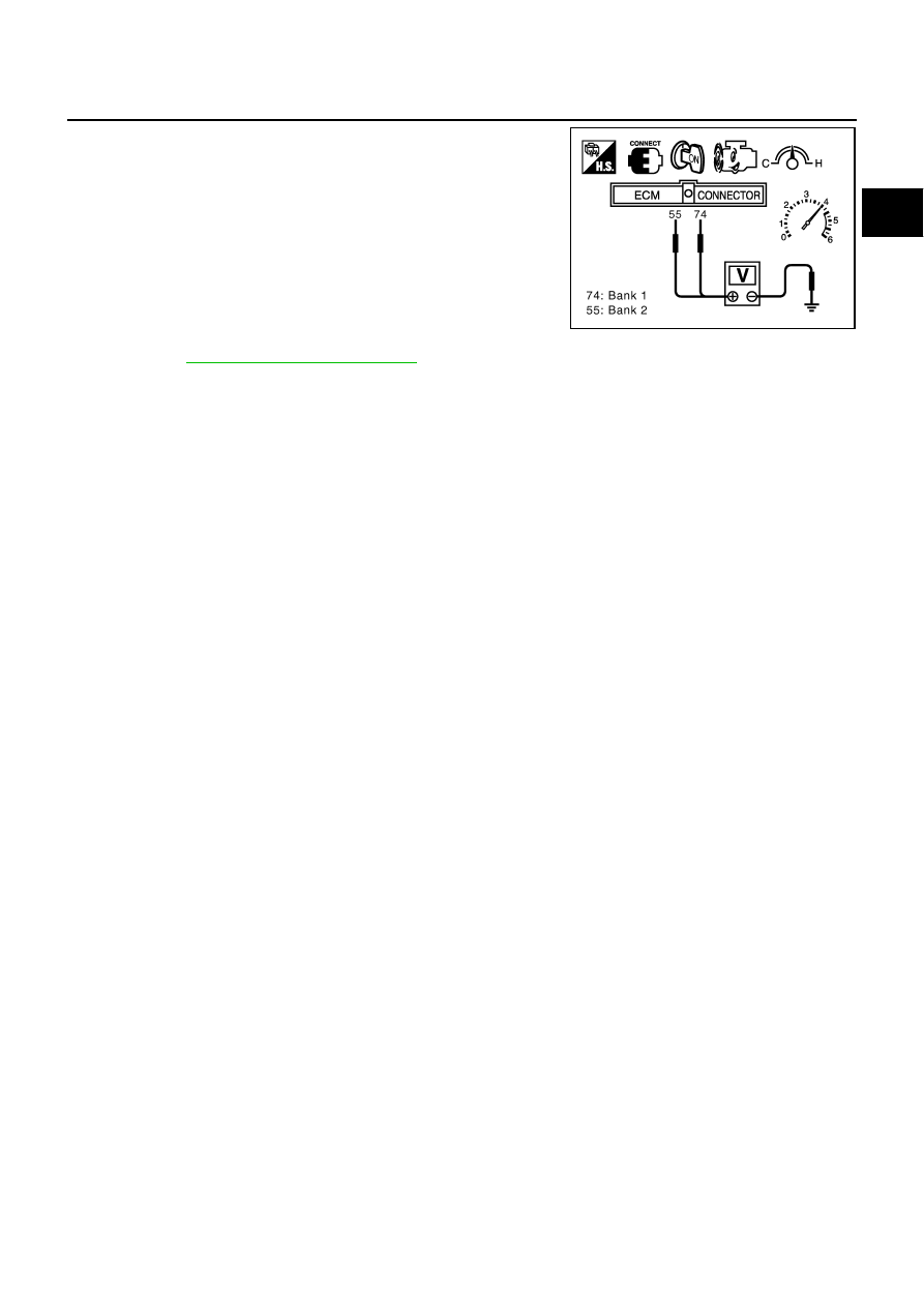
6.
Check the voltage when revving up to 4,000 rpm under no load
at least 10 times.
(Depress and release accelerator pedal as soon as possible.)
The voltage should be above 0.78V at least once during this
procedure.
If the voltage can be confirmed in step 6, step 7 is not nec-
essary.
7.
Keep vehicle at idling for 10 minutes, then check the voltage. Or
check the voltage when coasting from 80 km/h (50 MPH) in D
position.
The voltage should be above 0.78V at least once during this
procedure.
8.
EC-455, "Diagnostic Procedure"
PBIB1607E