Nissan Murano Z50 (2005 year). Manual - part 100


  Index      Manuals     Nissan Murano Z50 (2005 year) - Service and Repair Manual


Search            copyright infringement  


Content      ..     98      99      100      101     ..


Nissan Murano Z50 (2005 year). Manual - part 100


DTC P0453 EVAP CONTROL SYSTEM PRESSURE SENSOR

EC-355

C

D

E

F

G

H

I

J

K

L

M

A

EC

Revision: 2005 August

2005 Murano

DTC P0453 EVAP CONTROL SYSTEM PRESSURE SENSOR

PFP:25085

Component Description

ABS004HB

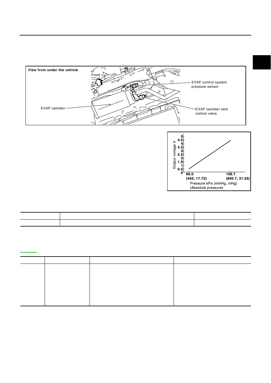
The EVAP control system pressure sensor detects pressure in the purge line. The sensor output voltage to the
ECM increases as pressure increases.

CONSULT-II Reference Value in Data Monitor Mode

ABS004HC

Specification data are reference values.

On Board Diagnosis Logic

ABS004HD

NOTE:
If DTC P0453 is displayed with DTC P1229, first perform the trouble diagnosis for DTC P1229. Refer to

EC-478

 .

PBIB1365E

PBIB1207E

MONITOR ITEM

CONDITION

SPECIFICATION

EVAP SYS PRES

Ignition switch: ON

Approx. 1.8 - 4.8V

DTC No.

Trouble diagnosis name

DTC detecting condition

Possible cause

P0453
0453

EVAP control system 
pressure sensor high 
input

An excessively high voltage from the sensor is 
sent to ECM.

Harness or connectors
(The sensor circuit is open or shorted.)

EVAP control system pressure sensor

EVAP canister vent control valve

EVAP canister

Rubber hose from EVAP canister vent 
control valve to vehicle frame

EC-356

DTC P0453 EVAP CONTROL SYSTEM PRESSURE SENSOR

Revision: 2005 August

2005 Murano

DTC Confirmation Procedure

ABS004HE

NOTE:
If DTC Confirmation Procedure has been previously conducted, always turn ignition switch OFF and wait at
least 10 seconds before conducting the next test.
TESTING CONDITION:
Always perform test at a temperature of 5

°

C (41

°

F) or more.

 WITH CONSULT-II

1.

Start engine and warm it up to normal operating temperature.

2.

Turn ignition switch OFF and wait at least 10 seconds.

3.

Turn ignition switch ON.

4.

Select “DATA MONITOR” mode with CONSULT-II.

5.

Make sure that “FUEL T/TMP SE” is more than 0

°

C (32

°

F).

6.

Start engine and wait at least 10 seconds.

7.

If 1st trip DTC is detected, go to 

EC-358, "Diagnostic Procedure"

.

 WITH GST

1.

Start engine and warm it up to normal operating temperature.

2.

Check that voltage between ECM terminal 107 (Fuel tank tem-
perature sensor signal) and ground is less than 4.2V.

3.

Turn ignition switch OFF and wait at least 10 seconds.

4.

Start engine and wait at least 10 seconds.

5.

Select Service $07 with GST.
If 1st trip DTC is detected, go to 

EC-358, "Diagnostic Procedure"

.

SEF194Y

PBIB1110E

DTC P0453 EVAP CONTROL SYSTEM PRESSURE SENSOR

EC-357

C

D

E

F

G

H

I

J

K

L

M

A

EC

Revision: 2005 August

2005 Murano

Wiring Diagram

ABS004HF

TBWB0276E

EC-358

DTC P0453 EVAP CONTROL SYSTEM PRESSURE SENSOR

Revision: 2005 August

2005 Murano

Specification data are reference values and are measured between each terminal and ground.

CAUTION:

Do not use ECM ground terminals when measuring input/output voltage. Doing so may result in dam-
age to the ECM's transistor. Use a ground other than ECM terminals, such as the ground.

Diagnostic Procedure

ABS004HG

1. 

CHECK GROUND CONNECTIONS

1.

Turn ignition switch OFF.

2.

Loosen and retighten two ground screws on the body.
Refer to 

EC-166, "Ground Inspection"

 .

OK or NG

OK

>> GO TO 2.

NG

>> Repair or replace ground connections.

2. 

CHECK CONNECTOR

1.

Disconnect EVAP control system pressure sensor harness connector.

2.

Check sensor harness connector for water.

OK or NG

OK

>> GO TO 3.

NG

>> Repair or replace harness connector.

TER-

MINAL 

NO.

WIRE 

COLOR

ITEM

CONDITION

DATA (DC Voltage)

32

BR

EVAP control system pres-
sure sensor

[Ignition switch: ON]

Approximately 1.8 - 4.8V

48

G/O

Sensor power supply
(EVAP control system pres-
sure sensor)

[Ignition switch: ON]

Approximately 5V

67

B

Sensor ground

[Engine is running]

Warm-up condition

Idle speed

Approximately 0V

PBIB1835E

Water should not exist.

PBIB1365E

DTC P0453 EVAP CONTROL SYSTEM PRESSURE SENSOR

EC-359

C

D

E

F

G

H

I

J

K

L

M

A

EC

Revision: 2005 August

2005 Murano

3. 

CHECK EVAP CONTROL SYSTEM PRESSURE SENSOR POWER SUPPLY CIRCUIT

1.

Turn ignition switch ON.

2.

Check voltage between EVAP control system pressure sensor
terminal 3 and ground with CONSULT-II or tester.

OK or NG

OK

>> GO TO 5.

NG

>> GO TO 4.

4. 

DETECT MALFUNCTIONING PART

Check the following.

Harness connectors B2, M9

Harness connectors M82, F102

Harness for open or short between EVAP control system pressure sensor and ECM

>> Repair open circuit or short to ground or short to power in harness or connectors.

5. 

CHECK EVAP CONTROL SYSTEM PRESSURE SENSOR GROUND CIRCUIT FOR OPEN AND 

SHORT

1.

Turn ignition switch OFF.

2.

Disconnect ECM harness connector.

3.

Check harness continuity between EVAP control system pressure sensor terminal 1 and ECM terminal
67.
Refer to Wiring Diagram.

4.

Also check harness for short to ground and short to power.

OK or NG

OK

>> GO TO 7.

NG

>> GO TO 6.

6. 

DETECT MALFUNCTIONING PART

Check the following.

Harness connectors B2, M9

Harness connectors M82, F102

Harness for open or short between EVAP control system pressure sensor and ECM

>> Repair open circuit or short to ground or short to power in harness or connectors.

Voltage: Approximately 5V

PBIB0138E

Continuity should exist.

EC-360

DTC P0453 EVAP CONTROL SYSTEM PRESSURE SENSOR

Revision: 2005 August

2005 Murano

7. 

CHECK EVAP CONTROL SYSTEM PRESSURE SENSOR INPUT SIGNAL CIRCUIT FOR OPEN AND 

SHORT

1.

Check harness continuity between ECM terminal 32 and EVAP control system pressure sensor terminal
2.
Refer to Wiring Diagram.

2.

Also check harness for short to ground and short to power.

OK or NG

OK

>> GO TO 9.

NG

>> GO TO 8.

8. 

DETECT MALFUNCTIONING PART

Check the following.

Harness connectors B2, M9

Harness connectors M82, F102

Harness for open or short between EVAP control system pressure sensor and ECM

>> Repair open circuit or short to ground or short to power in harness or connectors.

9. 

CHECK RUBBER TUBE

1.

Disconnect rubber tube connected to EVAP canister vent control valve.

2.

Check the rubber tube for clogging, vent and kinked.

OK or NG

OK

>> GO TO 10.

NG

>> Clean the rubber tube using an air blower, repair or replace rubber tube.

10. 

CHECK EVAP CANISTER VENT CONTROL VALVE

Refer to 

EC-344, "Component Inspection"

 .

OK or NG

OK

>> GO TO 11.

NG

>> Replace EVAP canister vent control valve.

11. 

CHECK EVAP CONTROL SYSTEM PRESSURE SENSOR

Refer to 

EC-362, "Component Inspection"

 .

OK or NG

OK

>> GO TO 12.

NG

>> Replace EVAP control system pressure sensor.

Continuity should exist.

DTC P0453 EVAP CONTROL SYSTEM PRESSURE SENSOR

EC-361

C

D

E

F

G

H

I

J

K

L

M

A

EC

Revision: 2005 August

2005 Murano

12. 

CHECK IF EVAP CANISTER SATURATED WITH WATER

1.

Remove EVAP canister with EVAP canister vent control valve and EVAP control system pressure sensor
attached.

2.

Check if water will drain from the EVAP canister.

Yes or No

Yes

>> GO TO 13.

No

>> GO TO 15.

13. 

CHECK EVAP CANISTER

Weigh the EVAP canister with the EVAP canister vent control valve and EVAP control system pressure sensor
attached.
The weight should be less than 2.1 kg (4.6 lb).

OK or NG

OK

>> GO TO 15.

NG

>> GO TO 14.

14. 

DETECT MALFUNCTIONING PART

Check the following.

EVAP canister for damage

EVAP hose between EVAP canister and vehicle frame for clogging or poor connection

>> Repair hose or replace EVAP canister.

15. 

CHECK INTERMITTENT INCIDENT

Refer to 

EC-157, "TROUBLE DIAGNOSIS FOR INTERMITTENT INCIDENT"

 .

>> INSPECTION END

PBIB1381E

EC-362

DTC P0453 EVAP CONTROL SYSTEM PRESSURE SENSOR

Revision: 2005 August

2005 Murano

Component Inspection

ABS004HH

EVAP CONTROL SYSTEM PRESSURE SENSOR

1.

Remove EVAP control system pressure sensor with its harness connector connected from EVAP canister.
Always replace O-ring with a new one.

2.

Install a vacuum pump to EVAP control system pressure sensor.

3.

Turn ignition switch ON and check output voltage between ECM
terminal 32 and ground under the following conditions.

CAUTION:

Always calibrate the vacuum pump gauge when using it.

Do not apply below -93.3 kPa (-700 mmHg, -27.56 inHg) or
pressure over 101.3 kPa (760 mmHg, 29.92 inHg).

4.

If NG, replace EVAP control system pressure sensor.

Applied vacuum kPa

(mmHg, inHg)

Voltage V

Not applied

1.8 - 4.8

-26.7 (-200, -7.87)

2.1 to 2.5V lower than above value

PBIB1173E

DTC P0455 EVAP CONTROL SYSTEM

EC-363

C

D

E

F

G

H

I

J

K

L

M

A

EC

Revision: 2005 August

2005 Murano

DTC P0455 EVAP CONTROL SYSTEM

PFP:14950

On Board Diagnosis Logic

ABS004HI

This diagnosis detects a very large leak (fuel filler cap fell off etc.) in EVAP system between the fuel tank and
EVAP canister purge volume control solenoid valve.

CAUTION:

Use only a genuine NISSAN fuel filler cap as a replacement. If an incorrect fuel filler cap is used,
the MIL may come on.

If the fuel filler cap is not tightened properly, the MIL may come on.

DTC No.

Trouble diagnosis name

DTC detecting condition

Possible cause

P0455
0455

EVAP control system 
gross leak detected

EVAP control system has a very large leak 
such as fuel filler cap fell off, EVAP control sys-
tem does not operate properly.

Fuel filler cap remains open or fails to 
close.

Incorrect fuel tank vacuum relief valve

Incorrect fuel filler cap used

Foreign matter caught in fuel filler cap.

Leak is in line between intake manifold 
and EVAP canister purge volume control 
solenoid valve.

Foreign matter caught in EVAP canister 
vent control valve.

EVAP canister or fuel tank leaks

EVAP purge line (pipe and rubber tube) 
leaks

EVAP purge line rubber tube bent.

Loose or disconnected rubber tube

EVAP canister vent control valve and the 
circuit

EVAP canister purge volume control 
solenoid valve and the circuit

Fuel tank temperature sensor

O-ring of EVAP canister vent control 
valve is missing or damaged.

EVAP control system pressure sensor

Refueling EVAP vapor cut valve

ORVR system leaks

PBIB1026E

EC-364

DTC P0455 EVAP CONTROL SYSTEM

Revision: 2005 August

2005 Murano

Use only a genuine NISSAN rubber tube as a replacement.

DTC Confirmation Procedure

ABS004HJ

CAUTION:

Never remove fuel filler cap during the DTC Confirmation Procedure.

NOTE:

Make sure that EVAP hoses are connected to EVAP canister purge volume control solenoid valve
properly.

If DTC Confirmation Procedure has been previously conducted, always turn ignition switch “OFF” and wait
at least 10 seconds before conducting the next test.

TESTING CONDITION:

Perform “DTC WORK SUPPORT” when the fuel level is between 1/4 and 3/4 full, and vehicle is
placed on flat level surface.

Open engine hood before conducting the following procedures.

 WITH CONSULT-II

1.

Tighten fuel filler cap securely until ratcheting sound is heard.

2.

Turn ignition switch ON.

3.

Turn ignition switch OFF and wait at least 10 seconds.

4.

Turn ignition switch ON and select “DATA MONITOR” mode with CONSULT-II.

5.

Make sure that the following conditions are met.
COOLAN TEMP/S: 0 - 70

°

C (32 - 158

°

F)

INT/A TEMP SE: 0 - 60

°

C (32 - 140

°

F)

6.

Select “EVP SML LEAK P0442/P1442” of “EVAPORATIVE SYSTEM” in “DTC WORK SUPPORT” mode
with CONSULT-II.
Follow the instruction displayed.

NOTE:
If the engine speed cannot be maintained within the range displayed on the CONSULT-II screen, go to

EC-70, "Basic Inspection"

 .

7.

Make sure that “OK” is displayed.
If “NG” is displayed, select “SELF-DIAG RESULTS” mode and
make sure that “EVAP GROSS LEAK [P0455]” is displayed. If it
is displayed, refer to 

EC-365, "Diagnostic Procedure"

 .

If P0442 is displayed, perform Diagnostic Procedure for DTC
P0442 

EC-326, "Diagnostic Procedure"

 .

PBIB0829E

SEC763C

DTC P0455 EVAP CONTROL SYSTEM

EC-365

C

D

E

F

G

H

I

J

K

L

M

A

EC

Revision: 2005 August

2005 Murano

 WITH GST

NOTE:
Be sure to read the explanation of Driving Pattern on 

EC-57, "Driving Pattern"

   before driving vehicle.

1.

Start engine.

2.

Drive vehicle according to Driving Pattern, 

EC-57, "Driving Pattern"

 .

3.

Stop vehicle.

4.

Turn ignition switch OFF, wait at least 10 seconds and then turn ignition switch ON.

5.

Select Service $07 with GST.

If P0441 is displayed on the screen, go to Diagnostic Procedure for DTC P0441, 

EC-321

 .

If P0442 is displayed on the screen, go to Diagnostic Procedure for DTC P0442, 

EC-326

 .

If P0455 is displayed on the screen, go to Diagnostic Procedure for DTC P0455, 

EC-365

 .

Diagnostic Procedure

ABS004HK

1. 

CHECK FUEL FILLER CAP DESIGN

1.

Turn ignition switch OFF.

2.

Check for genuine NISSAN fuel filler cap design.

OK or NG

OK

>> GO TO 2.

NG

>> Replace with genuine NISSAN fuel filler cap.

2. 

CHECK FUEL FILLER CAP INSTALLATION

Check that the cap is tightened properly by rotating the cap clockwise.

OK or NG

OK

>> GO TO 3.

NG

>> 1. Open fuel filler cap, then clean cap and fuel filler neck threads using air blower.

2. Retighten until ratcheting sound is heard.

3. 

CHECK FUEL FILLER CAP FUNCTION

Check for air releasing sound while opening the fuel filler cap.

OK or NG

OK

>> GO TO 5.

NG

>> GO TO 4.

4. 

CHECK FUEL TANK VACUUM RELIEF VALVE

Refer to 

EC-34, "FUEL TANK VACUUM RELIEF VALVE (BUILT INTO FUEL FULLER CAP)"

 .

OK or NG

OK

>> GO TO 5.

NG

>> Replace fuel filler cap with a genuine one.

SEF915U

EC-366

DTC P0455 EVAP CONTROL SYSTEM

Revision: 2005 August

2005 Murano

5. 

CHECK EVAP PURGE LINE

Check EVAP purge line (pipe, rubber tube, fuel tank and EVAP canister) for cracks, improper connection or
disconnection.
Refer to 

EC-32, "EVAPORATIVE EMISSION LINE DRAWING"

 .

OK or NG

OK

>> GO TO 6.

NG

>> Repair or reconnect the hose.

6. 

CLEAN EVAP PURGE LINE

Clean EVAP purge line (pipe and rubber tube) using air blower.

>> GO TO 7.

7. 

CHECK EVAP CANISTER VENT CONTROL VALVE

Check the following.

EVAP canister vent control valve is installed properly.
Refer to 

EC-35, "Removal and Installation"

 .

EVAP canister vent control valve.
Refer to 

EC-344, "Component Inspection"

 .

OK or NG

OK

>> GO TO 8.

NG

>> Repair or replace EVAP canister vent control valve and O-ring.

8. 

INSTALL THE PRESSURE PUMP

To locate the EVAP leak, install EVAP service port adapter and pres-
sure pump to EVAP service port securely.

NOTE:
Improper installation of the EVAP service port adapter to the
EVAP service port may cause leaking.

With CONSULT-II>>GO TO 9.
Without CONSULT-II>>GO TO 10.

PBIB2090E

SEF916U

DTC P0455 EVAP CONTROL SYSTEM

EC-367

C

D

E

F

G

H

I

J

K

L

M

A

EC

Revision: 2005 August

2005 Murano

9. 

CHECK FOR EVAP LEAK

 With CONSULT-II

1.

Turn ignition switch ON.

2.

Select “EVAP SYSTEM CLOSE” of “WORK SUPPORT” mode
with CONSULT-II.

3.

Touch “START” and apply pressure into the EVAP line until the
pressure indicator reaches the middle of the bar graph.

CAUTION:

Never use compressed air or a high pressure pump.

Do not exceed 4.12 kPa (0.042 kg/cm

2

 , 0.6 psi) of pres-

sure in the system.

4.

Using EVAP leak detector, locate the EVAP leak. For the leak
detector, refer to the instruction manual for more details.
Refer to 

EC-32, "EVAPORATIVE EMISSION LINE DRAWING"

 .

OK or NG

OK

>> GO TO 11.

NG

>> Repair or replace.

PEF917U

SEF200U

EC-368

DTC P0455 EVAP CONTROL SYSTEM

Revision: 2005 August

2005 Murano

10. 

CHECK FOR EVAP LEAK

 Without CONSULT-II

1.

Turn ignition switch OFF.

2.

Apply 12 volts DC to EVAP canister vent control valve. The valve will close. (Continue to apply 12 volts
until the end of test.)

3.

Pressurize the EVAP line using pressure pump with 1.3 to 2.7 kPa (10 to 20 mmHg, 0.39 to 0.79 inHg),
then remove pump and EVAP service port adapter.

CAUTION:

Never use compressed air or a high pressure pump.

Do not exceed 4.12 kPa (0.042 kg/cm

2

 , 0.6 psi) of pressure in the system.

4.

Using EVAP leak detector, locate the EVAP leak. For the leak
detector, refer to the instruction manual for more details. Refer
to 

EC-32, "EVAPORATIVE EMISSION LINE DRAWING"

 .

OK or NG

OK

>> GO TO 12.

NG

>> Repair or replace.

11. 

CHECK EVAP CANISTER PURGE VOLUME CONTROL SOLENOID VALVE OPERATION

 With CONSULT-II

1.

Disconnect vacuum hose to EVAP canister purge volume control solenoid valve at EVAP service port.

2.

Start engine.

3.

Perform “PURG VOL CONT/V” in “ACTIVE TEST” mode.

4.

Touch “Qu” on CONSULT-II screen to increase “PURG VOL
CONT/V” opening to 100%.

5.

Check vacuum hose for vacuum when revving engine up to
2,000 rpm.

OK or NG

OK

>> GO TO 14.

NG

>> GO TO 13.

PBIB1365E

SEF200U

PBIB1678E

DTC P0455 EVAP CONTROL SYSTEM

EC-369

C

D

E

F

G

H

I

J

K

L

M

A

EC

Revision: 2005 August

2005 Murano

12. 

CHECK EVAP CANISTER PURGE VOLUME CONTROL SOLENOID VALVE OPERATION

 Without CONSULT-II

1.

Start engine and warm it up to normal operating temperature.

2.

Stop engine.

3.

Disconnect vacuum hose to EVAP canister purge volume control solenoid valve at EVAP service port.

4.

Start engine and let it idle for at least 80 seconds.

5.

Check vacuum hose for vacuum when revving engine up to 2,000 rpm.

OK or NG

OK

>> GO TO 15.

NG

>> GO TO 13.

13. 

CHECK VACUUM HOSE

Check vacuum hoses for clogging or disconnection. Refer to 

EC-113, "Vacuum Hose Drawing"

 .

OK or NG

OK (With CONSULT-II)>>GO TO 14.
OK (Without CONSULT-II)>>GO TO 15.
NG

>> Repair or reconnect the hose.

14. 

CHECK EVAP CANISTER PURGE VOLUME CONTROL SOLENOID VALVE

 With CONSULT-II

1.

Start engine.

2.

Perform “PURG VOL CONT/V” in “ACTIVE TEST” mode with
CONSULT-II. Check that engine speed varies according to the
valve opening.

OK or NG

OK

>> GO TO 16.

NG

>> GO TO 15.

15. 

CHECK EVAP CANISTER PURGE VOLUME CONTROL SOLENOID VALVE

Refer to 

EC-338, "Component Inspection"

 .

OK or NG

OK

>> GO TO 16.

NG

>> Replace EVAP canister purge volume control solenoid valve.

16. 

CHECK FUEL TANK TEMPERATURE SENSOR

Refer to 

EC-270, "Component Inspection"

 .

OK or NG

OK

>> GO TO 17.

NG

>> Replace fuel level sensor unit.

Vacuum should exist.

PBIB1678E

EC-370

DTC P0455 EVAP CONTROL SYSTEM

Revision: 2005 August

2005 Murano

17. 

CHECK EVAP CONTROL SYSTEM PRESSURE SENSOR

Refer to 

EC-354, "Component Inspection"

 .

OK or NG

OK

>> GO TO 18.

NG

>> Replace EVAP control system pressure sensor.

18. 

CHECK EVAP/ORVR LINE

Check EVAP/ORVR line between EVAP canister and fuel tank for clogging, kink, looseness and improper con-
nection. For location, refer to 

EC-38, "ON BOARD REFUELING VAPOR RECOVERY (ORVR)"

 .

OK or NG

OK

>> GO TO 19.

NG

>> Repair or replace hoses and tubes.

19. 

CHECK RECIRCULATION LINE

Check recirculation line between filler neck tube and fuel tank for clogging, kink, cracks, looseness and
improper connection.

OK or NG

OK

>> GO TO 20.

NG

>> Repair or replace hose, tube or filler neck tube.

20. 

CHECK REFUELING EVAP VAPOR CUT VALVE

Refer to 

EC-41, "REFUELING EVAP VAPOR CUT VALVE"

 .

OK or NG

OK

>> GO TO 21.

NG

>> Replace refueling EVAP vapor cut valve with fuel tank. 

21. 

CHECK INTERMITTENT INCIDENT

Refer to 

EC-157, "TROUBLE DIAGNOSIS FOR INTERMITTENT INCIDENT"

 .

>> INSPECTION END


Content      ..     98      99      100      101     ..