Nissan Murano Z50 (2005 year). Manual - part 94


  Index      Manuals     Nissan Murano Z50 (2005 year) - Service and Repair Manual


Search            copyright infringement  


Content      ..     92      93      94      95     ..


Nissan Murano Z50 (2005 year). Manual - part 94


DTC P0172, P0175 FUEL INJECTION SYSTEM FUNCTION

EC-259

C

D

E

F

G

H

I

J

K

L

M

A

EC

Revision: 2005 August

2005 Murano

Diagnostic Procedure

ABS00A5W

1. 

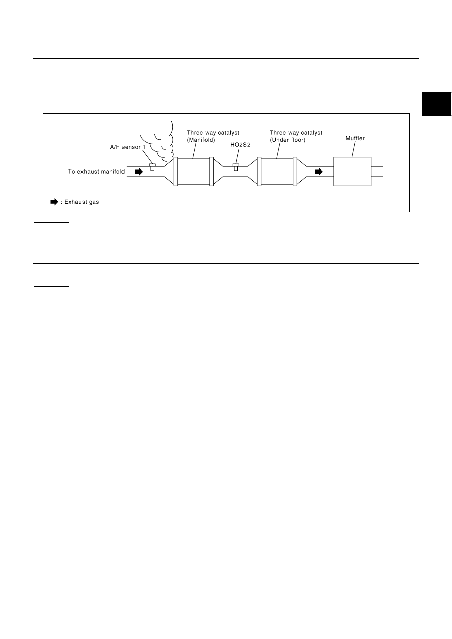
CHECK EXHAUST GAS LEAK

1.

Start engine and run it at idle.

2.

Listen for an exhaust gas leak before three way catalyst (manifold).

OK or NG

OK

>> GO TO 2.

NG

>> Repair or replace.

2. 

CHECK FOR INTAKE AIR LEAK

Listen for an intake air leak after the mass air flow sensor.

OK or NG

OK

>> GO TO 3.

NG

>>  Repair or replace.

PBIB1216E

EC-260

DTC P0172, P0175 FUEL INJECTION SYSTEM FUNCTION

Revision: 2005 August

2005 Murano

3. 

CHECK A/F SENSOR 1 INPUT SIGNAL CIRCUIT

1.

Turn ignition switch OFF.

2.

Disconnect corresponding A/F sensor 1 harness connector.

3.

Disconnect ECM harness connector.

4.

Check harness continuity between the following terminals.
Refer to Wiring Diagram.

5.

Check harness continuity between the following terminals and ground.
Refer to Wiring Diagram.

6.

Also check harness for short to power.

OK or NG

OK

>> GO TO 4.

NG

>> Repair open circuit or short to ground or short to power in harness or connectors.

Bank 1

A/F sensor 1 terminal

ECM terminal

1

16

2

75

5

35

6

56

Bank 2

1

76

2

77

5

57

6

58

Continuity should exist.

Bank 1

Bank 2

A/F sensor 1 terminal

ECM terminal

A/F sensor 1 terminal

ECM terminal

1

16

1

76

2

75

2

77

5

35

5

57

6

56

6

58

Continuity should not exist.

PBIB2293E

DTC P0172, P0175 FUEL INJECTION SYSTEM FUNCTION

EC-261

C

D

E

F

G

H

I

J

K

L

M

A

EC

Revision: 2005 August

2005 Murano

4. 

CHECK FUEL PRESSURE

1.

Release fuel pressure to zero. Refer to 

EC-92, "FUEL PRESSURE RELEASE"

 .

2.

Install fuel pressure gauge and check fuel pressure. Refer to 

EC-92, "FUEL PRESSURE CHECK"

 .

OK or NG

OK (With CONSULT-II)>>GO TO 6.
OK (Without CONSULT-II)>>GO TO 7.
NG

>> GO TO 5.

5. 

DETECT MALFUNCTIONING PART

Check the following.

Fuel pump and circuit (Refer to 

EC-670, "FUEL PUMP CIRCUIT"

 .)

Fuel pressure regulator (Refer to 

EC-92, "FUEL PRESSURE RELEASE"

 .)

>> Repair or replace.

6. 

CHECK MASS AIR FLOW SENSOR

 With CONSULT-II

1.

Install all removed parts.

2.

Check “MASS AIR FLOW” in “DATA MONITOR” mode with CONSULT-II.

OK or NG

OK

>> GO TO 8.

NG

>> Check connectors for rusted terminals or loose connections in the mass air flow sensor circuit or

ground. Refer to 

EC-183, "DTC P0101 MAF SENSOR"

 .

7. 

CHECK MASS AIR FLOW SENSOR

 With GST

1.

Install all removed parts.

2.

Check mass air flow sensor signal in Service $01 with GST.

OK or NG

OK (P0172)>>GO TO 9.
OK (P0175)>>GO TO 11.
NG

>> Check connectors for rusted terminals or loose connections in the mass air flow sensor circuit or

ground. Refer to 

EC-183, "DTC P0101 MAF SENSOR"

 .

At idling: Approximately 350 kPa (3.57 kg/cm

2

 , 51 psi)

2.0 - 6.0 g·m/sec:

at idling

7.0 - 20.0 g·m/sec:

at 2,500 rpm

2.0 - 6.0 g·m/sec:

at idling

7.0 - 20.0 g·m/sec:

at 2,500 rpm

EC-262

DTC P0172, P0175 FUEL INJECTION SYSTEM FUNCTION

Revision: 2005 August

2005 Murano

8. 

CHECK FUNCTION OF INJECTOR

 With CONSULT-II

1.

Start engine.

2.

Perform “POWER BALANCE” in “ACTIVE TEST” mode with
CONSULT-II.

3.

Make sure that each circuit produces a momentary engine
speed drop.

OK or NG

OK

>> GO TO 12.

NG

>> Perform trouble diagnosis for INJECTOR CIRCUIT, refer to 

EC-663, "INJECTOR CIRCUIT"

 .

PBIB0133E

DTC P0172, P0175 FUEL INJECTION SYSTEM FUNCTION

EC-263

C

D

E

F

G

H

I

J

K

L

M

A

EC

Revision: 2005 August

2005 Murano

9. 

CHECK FUNCTION OF INJECTOR-I

 Without CONSULT-II

1.

Stop engine.

2.

Disconnect harness connector F29, F201

3.

Turn ignition switch ON.

4.

Check voltage between harness connector F29 terminal 5 and
ground with CONSULT-II or tester.

5.

Turn ignition switch OFF.

6.

Disconnect ECM harness connector.

7.

Check harness continuity between harness connector F29 ter-
minals and ECM terminals as follows.
Refer to Wiring Diagram.

8.

Also check harness for short to ground and short to power.

OK or NG

OK

>> GO TO 10.

NG

>> Perform trouble diagnosis for INJECTOR CIRCUIT, refer to 

EC-663, "INJECTOR CIRCUIT"

 .

10. 

CHECK FUNCTION OF INJECTOR-II

Provide battery voltage between harness connector F201 as follows
and then interrupt it. Listen to each injector operating sound.

OK or NG

OK

>> GO TO 12.

NG

>> Perform trouble diagnosis for INJECTOR CIRCUIT, refer to 

EC-663, "INJECTOR CIRCUIT"

 .

PBIB2618E

Voltage: Battery voltage

Cylinder

Harness connector F29 

terminal

ECM terminal

1

6

23

3

2

22

5

1

21

Continuity should exist.

PBIB2323E

Cylinder

Harness connector F201 terminal

(+)

(–)

1

5

6

3

5

2

5

5

1

Operating sound should exist.

PBIB2324E

EC-264

DTC P0172, P0175 FUEL INJECTION SYSTEM FUNCTION

Revision: 2005 August

2005 Murano

11. 

CHECK FUNCTION OF INJECTOR

1.

Start engine.

2.

Listen to injectors No.2, No.4, No.6 operating sound.

OK or NG

OK

>> GO TO 12.

NG

>> Perform trouble diagnosis for INJECTOR CIRCUIT, refer

to 

EC-663, "INJECTOR CIRCUIT"

 .

12. 

CHECK INJECTOR

1.

Remove injector assembly. Refer to 

EM-41, "FUEL INJECTOR AND FUEL TUBE"

 .

Keep fuel hose and all injectors connected to injector gallery.

2.

Confirm that the engine is cooled down and there are no fire hazards near the vehicle.

3.

Disconnect all injector harness connectors.

4.

Disconnect all ignition coil harness connectors.

5.

Prepare pans or saucers under each injectors.

6.

Crank engine for about 3 seconds.
Make sure fuel does not drip from injector.

OK or NG

OK (Does not drip.)>>GO TO 13.
NG (Drips.)>>Replace the injectors from which fuel is dripping. Always replace O-ring with new one.

13. 

CHECK INTERMITTENT INCIDENT

Refer to 

EC-157, "TROUBLE DIAGNOSIS FOR INTERMITTENT INCIDENT"

 .

>> INSPECTION END

Clicking noise should exist.

PBIB1986E

DTC P0181 FTT SENSOR

EC-265

C

D

E

F

G

H

I

J

K

L

M

A

EC

Revision: 2005 August

2005 Murano

DTC P0181 FTT SENSOR

PFP:22630

Component Description

ABS004F2

The fuel tank temperature sensor is used to detect the fuel tempera-
ture inside the fuel tank. The sensor modifies a voltage signal from
the ECM. The modified signal returns to the ECM as the fuel temper-
ature input. The sensor uses a thermistor which is sensitive to the
change in temperature. The electrical resistance of the thermistor
decreases as temperature increases.

<Reference data>

*: This data is reference value and is measured between ECM terminal 107 (Fuel
tank temperature sensor) and ground.

CAUTION:

Do not use ECM ground terminals when measuring input/output
voltage. Doing so may result in damage to the ECM's transistor.
Use a ground other than ECM terminals, such as the ground.

On Board Diagnosis Logic

ABS004F3

DTC Confirmation Procedure

ABS004F4

NOTE:
If DTC Confirmation Procedure has been previously conducted, always turn ignition switch OFF and wait at
least 10 seconds before conducting the next test.

 WITH CONSULT-II

1.

Turn ignition switch ON.

2.

Select “DATA MONITOR” mode with CONSULT-II.

3.

Wait at least 10 seconds.
If the result is NG, go to 

EC-268, "Diagnostic Procedure"

  .

If the result is OK, go to following step.

4.

Check “COOLAN TEMP/S” value.
If “COOLAN TEMP/S” is less than 60

°

C (140

°

F), the result will

be OK.
If “COOLAN TEMP/S” is above 60

°

C (140

°

F), go to the following

step.

5.

Cool engine down until “COOLAN TEMP/S” is less than 60

°

C

(140

°

F).

6.

Wait at least 10 seconds.

7.

If 1st trip DTC is detected, go to 

EC-268, "Diagnostic Procedure"

  .

PBIB1356E

Fluid temperature

°

C (

°

F)

Voltage*

V

Resistance

k

20 (68)

3.5

2.3 - 2.7

50 (122)

2.2

0.79 - 0.90

SEF012P

DTC No.

Trouble diagnosis name

DTC detecting condition

Possible cause

P0181
0181

Fuel tank temperature 
sensor circuit range/
performance

Rationally incorrect voltage from the sensor is 
sent to ECM, compared with the voltage sig-
nals from engine coolant temperature sensor 
and intake air temperature sensor.

Harness or connectors
(The sensor circuit is open or shorted)

Fuel tank temperature sensor

SEF174Y

EC-266

DTC P0181 FTT SENSOR

Revision: 2005 August

2005 Murano

 WITH GST

Follow the procedure “WITH CONSULT-II” above.

DTC P0181 FTT SENSOR

EC-267

C

D

E

F

G

H

I

J

K

L

M

A

EC

Revision: 2005 August

2005 Murano

Wiring Diagram

ABS004F5

TBWB0270E

EC-268

DTC P0181 FTT SENSOR

Revision: 2005 August

2005 Murano

Diagnostic Procedure

ABS004F6

1. 

CHECK GROUND CONNECTIONS

1.

Turn ignition switch OFF.

2.

Loosen and retighten two ground screws on the body.
Refer to 

EC-166, "Ground Inspection"

 .

OK or NG

OK

>> GO TO 2.

NG

>> Repair or replace ground connections.

2. 

CHECK UNIFIED METER AND A/C AMP.

Refer to 

DI-32, "SELF-DIAGNOSTIC RESULTS"

 .

OK or NG

OK

>> GO TO 3.

NG

>> Go to 

DI-21, "Fuel Level Sensor Signal Inspection"

  .

3. 

CHECK FUEL TANK TEMPERATURE SENSOR POWER SUPPLY CIRCUIT

1.

Disconnect “fuel level sensor unit and fuel pump” harness con-
nector.

2.

Turn ignition switch ON.

3.

Check voltage between “fuel level sensor unit and fuel pump”
terminal 4 and ground with CONSULT-II or tester.

OK or NG

OK

>> GO TO 5.

NG

>> GO TO 4.

PBIB1835E

PBIB1357E

Voltage: Approximately 5V

PBIB0932E

DTC P0181 FTT SENSOR

EC-269

C

D

E

F

G

H

I

J

K

L

M

A

EC

Revision: 2005 August

2005 Murano

4. 

DETECT MALFUNCTIONING PART

Check the following.

Harness connectors M9, B2

Harness for open or short between ECM and “fuel level sensor unit and fuel pump”

>> Repair open circuit or short to ground or short to power in harness or connector.

5. 

CHECK FUEL TANK TEMPERATURE SENSOR GROUND CIRCUIT FOR OPEN AND SHORT

1.

Turn ignition switch OFF.

2.

Disconnect “unified meter and A/C amp.” harness connector.

3.

Check harness continuity between “fuel level sensor unit and fuel pump” terminal 5 and “unified meter and
A/C amp.” terminal 36. Refer to Wiring Diagram.

4.

Also check harness for short to ground and short to power.

OK or NG

OK

>> GO TO 7.

NG

>> GO TO 6.

6. 

DETECT MALFUNCTIONING PART

Check the following.

Harness connectors B2, M9

Harness for open or short between “fuel level sensor unit and fuel pump” and “unified meter and A/C
amp.”

>> Repair open circuit or short to ground or short to power in harness or connector.

7. 

CHECK FUEL TANK TEMPERATURE SENSOR

Refer to 

EC-270, "Component Inspection"

  .

OK or NG

OK

>> GO TO 8.

NG

>> Replace “fuel level sensor unit and fuel pump”.

8. 

CHECK INTERMITTENT INCIDENT

Refer to 

EC-157, "TROUBLE DIAGNOSIS FOR INTERMITTENT INCIDENT"

  .

>> INSPECTION END

Continuity should exist.

EC-270

DTC P0181 FTT SENSOR

Revision: 2005 August

2005 Murano

Component Inspection

ABS004F7

FUEL TANK TEMPERATURE SENSOR

1.

Remove fuel level sensor unit.

2.

Check resistance between “fuel level sensor unit and fuel pump”
terminals 4 and 5 by heating with hot water or heat gun as
shown in the figure.

Removal and Installation

ABS004F8

FUEL TANK TEMPERATURE SENSOR

Refer to 

FL-4, "FUEL LEVEL SENSOR UNIT, FUEL FILTER AND FUEL PUMP ASSEMBLY"

  .

Temperature 

°

C (

°

F)

Resistance k

20 (68)

2.3 - 2.7

50 (122)

0.79 - 0.90

PBIB0931E

DTC P0182, P0183 FTT SENSOR

EC-271

C

D

E

F

G

H

I

J

K

L

M

A

EC

Revision: 2005 August

2005 Murano

DTC P0182, P0183 FTT SENSOR

PFP:22630

Component Description

ABS004F9

The fuel tank temperature sensor is used to detect the fuel tempera-
ture inside the fuel tank. The sensor modifies a voltage signal from
the ECM. The modified signal returns to the ECM as the fuel temper-
ature input. The sensor uses a thermistor which is sensitive to the
change in temperature. The electrical resistance of the thermistor
decreases as temperature increases.

<Reference data>

*: This data is reference value and is measured between ECM terminal 107 (Fuel
tank temperature sensor) and ground.

CAUTION:

Do not use ECM ground terminals when measuring input/output
voltage. Doing so may result in damage to the ECM's transistor.
Use a ground other than ECM terminals, such as the ground.

On Board Diagnosis Logic

ABS004FA

DTC Confirmation Procedure

ABS004FB

NOTE:
If DTC Confirmation Procedure has been previously conducted, always turn ignition switch OFF and wait at
least 10 seconds before conducting the next test.

 WITH CONSULT-II

1.

Turn ignition switch ON.

2.

Select “DATA MONITOR” mode with CONSULT-II.

3.

Wait at least 5 seconds.

4.

If 1st trip DTC is detected, go to 

EC-273, "Diagnostic Procedure"

.

 WITH GST

Follow the procedure “WITH CONSULT-II” above.

PBIB1356E

Fluid temperature

°

C (

°

F)

Voltage*

V

Resistance

k

20 (68)

3.5

2.3 - 2.7

50 (122)

2.2

0.79 - 0.90

SEF012P

DTC No.

Trouble diagnosis name

DTC detecting condition

Possible cause

P0182
0182

Fuel tank temperature 
sensor circuit low input

An excessively low voltage from the sensor is 
sent to ECM.

Harness or connectors
(The sensor circuit is open or shorted.)

Fuel tank temperature sensor

P0183
0183

Fuel tank temperature 
sensor circuit high input

An excessively high voltage from the sensor is 
sent to ECM.

SEF174Y

EC-272

DTC P0182, P0183 FTT SENSOR

Revision: 2005 August

2005 Murano

Wiring Diagram

ABS004FC

TBWB0270E

DTC P0182, P0183 FTT SENSOR

EC-273

C

D

E

F

G

H

I

J

K

L

M

A

EC

Revision: 2005 August

2005 Murano

Diagnostic Procedure

ABS004FD

1. 

CHECK GROUND CONNECTIONS

1.

Turn ignition switch OFF.

2.

Loosen and retighten two ground screws on the body.
Refer to 

EC-166, "Ground Inspection"

 .

OK or NG

OK

>> GO TO 2.

NG

>> Repair or replace ground connections.

2. 

CHECK DTC WITH “UNIFIED METER AND A/C AMP.”

Refer to 

DI-32, "SELF-DIAGNOSTIC RESULTS"

 .

OK or NG

OK

>> GO TO 3.

NG

>> Go to 

DI-21, "Fuel Level Sensor Signal Inspection"

 .

3. 

CHECK FUEL TANK TEMPERATURE SENSOR POWER SUPPLY CIRCUIT

1.

Disconnect “fuel level sensor unit and fuel pump” harness con-
nector.

2.

Turn ignition switch ON.

3.

Check voltage between “fuel level sensor unit and fuel pump”
terminal 4 and ground with CONSULT-II or tester.

OK or NG

OK

>> GO TO 5.

NG

>> GO TO 4.

PBIB1835E

PBIB1357E

Voltage: Approximately 5V

PBIB0932E

EC-274

DTC P0182, P0183 FTT SENSOR

Revision: 2005 August

2005 Murano

4. 

DETECT MALFUNCTIONING PART

Check the following.

Harness connectors M9, B2

Harness for open or short between ECM and “fuel level sensor unit and fuel pump”

>> Repair open circuit or short to ground or short to power in harness or connector.

5. 

CHECK FUEL TANK TEMPERATURE SENSOR GROUND CIRCUIT FOR OPEN AND SHORT

1.

Turn ignition switch OFF.

2.

Disconnect “unified meter and A/C amp.” harness connector.

3.

Check harness continuity between “fuel level sensor unit and fuel pump” terminal 5 and “unified meter and
A/C amp.” terminal 36. Refer to Wiring Diagram.

4.

Also check harness for short to ground and short to power.

OK or NG

OK

>> GO TO 7.

NG

>> GO TO 6.

6. 

DETECT MALFUNCTIONING PART

Check the following.

Harness connectors B2, M9

Harness for open or short between “fuel level sensor unit and fuel pump” and “unified meter and A/C
amp.”

>> Repair open circuit or short to ground or short to power in harness or connector.

7. 

CHECK FUEL TANK TEMPERATURE SENSOR

Refer to 

EC-270, "Component Inspection"

 .

OK or NG

OK

>> GO TO 8.

NG

>> Replace “fuel level sensor unit and fuel pump”.

8. 

CHECK INTERMITTENT INCIDENT

Refer to 

EC-157, "TROUBLE DIAGNOSIS FOR INTERMITTENT INCIDENT"

 .

>> INSPECTION END

Component Inspection

ABS004FE

FUEL TANK TEMPERATURE SENSOR

1.

Remove fuel level sensor unit.

Continuity should exist.


Content      ..     92      93      94      95     ..