Nissan Murano Z50 (2005 year). Manual - part 92
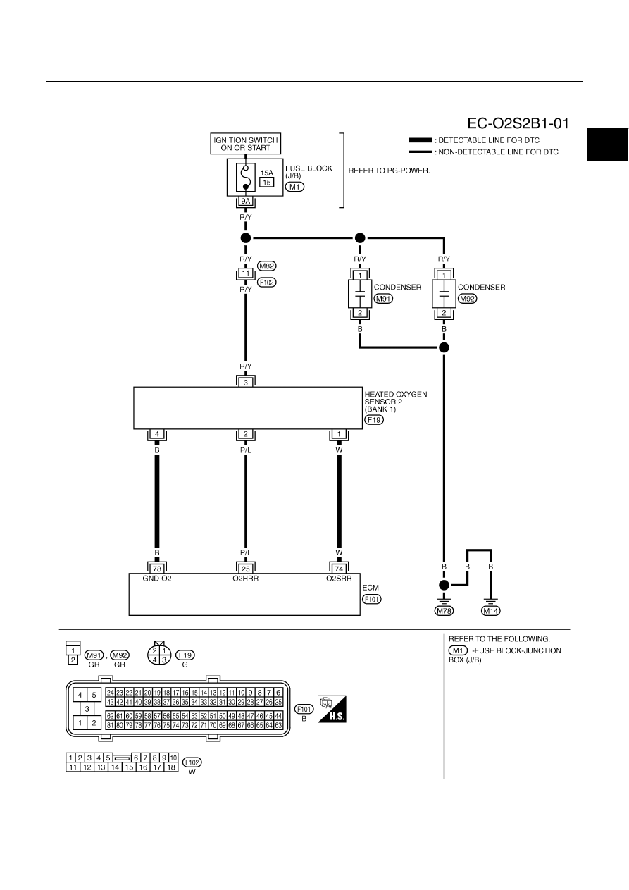
DTC P0138, P0158 HO2S2
EC-227
C
D
E
F
G
H
I
J
K
L
M
A
EC
Revision: 2005 August
2005 Murano
Wiring Diagram
ABS004EH
BANK 1
TBWA0694E
|
|
|
DTC P0138, P0158 HO2S2 EC-227 C D E F G H I J K L M A EC Revision: 2005 August 2005 Murano Wiring Diagram ABS004EH BANK 1 TBWA0694E |