Nissan Murano Z50 (2005 year). Manual - part 73


  Index      Manuals     Nissan Murano Z50 (2005 year) - Service and Repair Manual


Search            copyright infringement  


Content      ..     71      72      73      74     ..


Nissan Murano Z50 (2005 year). Manual - part 73


COMBINATION METERS

DI-5

C

D

E

F

G

H

I

J

L

M

A

B

DI

Revision: 2005 August

2005 Murano

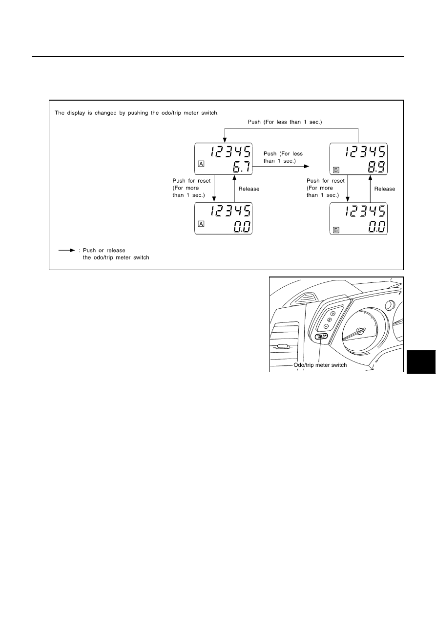
HOW TO CHANGE THE DISPLAY FOR ODO/TRIP METER

The vehicle speed signal and the memory signals from the meter memory circuit are processed by the
combination meter and the mileage is displayed.

Depressing the odo/trip meter switch toggles the mode in the following order.

The odo/trip meter display mode toggling and trip display reset-
ting can be identified by the amount of time that elapses from
pressing the odo/trip meter switch to releasing it.

When resetting with trip A displayed, only trip A display is reset
(Trip B operates the same way).

SEL175W

PKIA2480E

DI-6

COMBINATION METERS

Revision: 2005 August

2005 Murano

POWER SUPPLY AND GROUND CIRCUIT

Power is supplied at all times

through 10A fuse [No. 19, located in the fuse block (J/B)]

to unified meter and A/C amp. terminal 21,

through 10A fuse [No. 21, located in the fuse block (J/B)]

to combination meter terminal 21.

With the ignition switch in the ON or START position, power is supplied

through 10A fuse [No. 14, located in the fuse block (J/B)]

to combination meter terminal 20,

through 10A fuse [No. 12, located in the fuse block (J/B)]

to unified meter and A/C amp. terminal 22.

With the ignition switch in the ON position, power is supplied

through 15A fuse [No. 10, located in the fuse block (J/B)], and

through 15A fuse [No. 11, located in the fuse block (J/B)]

to unified meter and A/C amp. terminal 46.

Ground is supplied

to combination meter terminals 22, 23 and 24

through grounds M14 and M78,

to unified meter and A/C amp. terminals 29 and 30

through grounds M14 and M78.

SPEEDOMETER

ABS actuator and electric unit (control unit) provides a vehicle speed signal to the unified meter and A/C amp.
with CAN communication line. After unified meter and A/C amp. received the vehicle speed signal, it changes
the signal to 8 pulse signal and provides the 8 pulse signal to the combination meter for the speedometer.

TACHOMETER

The tachometer indicates engine speed in revolutions per minute (rpm).
ECM provides an engine speed signal to unified meter and A/C amp. with CAN communication line. Unified
meter and A/C amp. provides an engine speed signal to combination meter for tachometer with communica-
tion line between unified meter and A/C amp. and combination meter.

WATER TEMPERATURE GAUGE

The water temperature gauge indicates the engine coolant temperature.
ECM provides a engine coolant temperature signal to unified meter and A/C amp. with CAN communication
line. Unified meter and A/C amp. provides a water temperature signal to combination meter for water temper-
ature gauge with communication line between unified meter and A/C amp. and combination meter.

FUEL GAUGE

The fuel gauge indicates the approximate fuel level in the fuel tank.
The fuel gauge is regulated by a variable ground signal supplied

from unified meter and A/C amp. terminal 36

through the fuel level sensor unit and fuel pump (main) terminals 5 and 7

through the fuel level sensor unit (sub), and

through the fuel level sensor unit and fuel pump (main) terminals 6 and 2

to unified meter and A/C amp. terminal 28 for the fuel gauge.

Unified meter and A/C amp. provides an fuel level signal to combination meter for fuel gauge with communica-
tion line between unified meter and A/C amp. and combination meter.

COMBINATION METERS

DI-7

C

D

E

F

G

H

I

J

L

M

A

B

DI

Revision: 2005 August

2005 Murano

Component Parts and Harness Connector Location

AKS00D4Q

PKIA2477E

DI-8

COMBINATION METERS

Revision: 2005 August

2005 Murano

Arrangement of Combination Meter

AKS00D4R

PKIB4911E

COMBINATION METERS

DI-9

C

D

E

F

G

H

I

J

L

M

A

B

DI

Revision: 2005 August

2005 Murano

Circuit Diagram

AKS00D4S

TKWB0480E

DI-10

COMBINATION METERS

Revision: 2005 August

2005 Murano

Wiring Diagram — METER —

AKS00D4T

TKWB0481E

COMBINATION METERS

DI-11

C

D

E

F

G

H

I

J

L

M

A

B

DI

Revision: 2005 August

2005 Murano

TKWB0902E

DI-12

COMBINATION METERS

Revision: 2005 August

2005 Murano

Terminals and Reference Value for Combination Meter

AKS00D4U

Terminal 

No.

Wire 

color

Item

Measuring condition

Reference value (V)

Ignition 

switch

Operation or condition

14

V/W

Vehicle speed signal
(8-pulse)

ON

Speedometer operated
[When vehicle speed is 
approx. 40 km/h (25 MPH)]

NOTE:
Maximum voltage may be 5 V due to 
specifications (connected units).

15

R/W

Illumination signal

ON

Lighting switch ON, then 
operate the illumination 
control switch.

<e.g.> When brightness level is midway.

Lighting switch OFF

Approx. 0

18

R/L

TX communication line (To 
unified meter and A/C 
amp.)

ON

19

R/B

RX communication line 
(From unified meter and A/
C amp.)

ON

20

O

Ignition switch ON or 
START

ON

Battery voltage

21

Y/R

Battery power supply

OFF

Battery voltage

22

B

Ground

ON

Approx. 0

23

24

27

Illumination control switch 
(+)

Refer to 

DI-23, "Odo/Trip Meter and Illu-

mination Control Switch Inspection"

 .

28

Illumination control switch 
(–)

29

Odo/trip meter switch

30

Odo/trip meter and illumi-
nation control switch 
ground

PKIA1935E

SKIA5872E

SKIA3361E

SKIA3362E

COMBINATION METERS

DI-13

C

D

E

F

G

H

I

J

L

M

A

B

DI

Revision: 2005 August

2005 Murano

Terminals and Reference Value for Unified Meter and A/C Amp.

AKS00D4V

Terminal 

No.

Wire 

color

Item

Measuring condition

Reference value (V)

Ignition 

switch

Operation or condition

1

L

CAN H

9

R/B

TX communication line 
(To combination meter)

ON

11

Y

CAN L

19

R/L

RX communication line 
(From combination meter)

ON

21

Y/R

Battery power supply

OFF

Battery voltage

22

G

Ignition switch ON or 
START

ON

Battery voltage

26

V/W

Vehicle speed signal
(8-pulse)

ON

Speedometer operated
[When vehicle speed is 
approx. 40 km/h (25 MPH)]

NOTE:
Maximum voltage may be 5 V due to 
specifications (connected units).

28

G/B

Fuel level sensor signal

Refer to 

DI-25, "FUEL LEVEL SEN-

SOR UNIT CHECK"

 .

29

B

Ground (For power)

ON

Approx. 0

30

Ground

ON

Approx. 0

36

B/W

Fuel level sensor signal 
ground

ON

Approx. 0

46

W/L

Ignition switch ON

ON

Battery voltage

SKIA3362E

SKIA3361E

PKIA1935E

DI-14

COMBINATION METERS

Revision: 2005 August

2005 Murano

Self-Diagnosis Mode of Combination Meter

AKS00D4W

SELF-DIAGNOSIS FUNCTION

Odo/trip meter segment and CVT indicator segment operation can be checked in self-diagnosis mode.

Meters/gauges can be checked in self-diagnosis mode.

OPERATION PROCEDURE

1.

Turn ignition switch ON, and switch the odo/trip meter to “trip A” or “trip B”.

NOTE:
If the diagnosis function is activated with the trip meter A displayed, the mileage on the trip meter A will
indicate 0000.0 miles, but the actual trip mileage will be retained. (Trip B operates the same way.)

2.

Turn ignition switch OFF.

3.

While pushing the odo/trip meter switch, turn ignition switch ON
again.

4.

Make sure the trip meter displays “0000.0”.

5.

Push the odo/trip meter switch at least 3 times. (Within 7 sec-
onds after the ignition switch is turned ON.)

6.

All the segments on the odo/trip meter and CVT indicator illuminate, and simultaneously the low-fuel
warning lamp indicator illuminates. At this time, the unified meter control unit is turned to diagnosis mode.

7.

Push the odo/trip meter switch. Each meter/gauge should indi-
cate as shown in the figure while pushing odo/trip meter switch.
(At this time, the low-fuel warning lamp goes off.)

CONSULT-II Function (METER A/C AMP)

AKS00D4X

Refer to 

DI-31, "CONSULT-II Function (METER A/C AMP)"

  in “UNIFIED METER AND A/C AMP”.

PKIA2480E

SKIA4428E

PKIA2482E

COMBINATION METERS

DI-15

C

D

E

F

G

H

I

J

L

M

A

B

DI

Revision: 2005 August

2005 Murano

Trouble Diagnosis

AKS00D4Y

HOW TO PERFORM TROUBLE DIAGNOSIS

1.

Confirm the symptom or customer complaint.

2.

Perform diagnosis according to preliminary check. Refer to 

DI-15, "PRELIMINARY CHECK"

 .

3.

According to the symptom chart, repair or replace the cause of the symptom. Refer to 

DI-16, "Symptom

Chart 1"

 .

4.

Does the meter operate normally? If so, GO TO 5. If not, GO TO 2.

5.

INSPECTION END

PRELIMINARY CHECK

1. 

CHECK SELF-DIAGNOSTIC RESULTS OF UNIFIED METER AND A/C AMP.

Select “METER A/C AMP” on CONSULT-II, and perform self-diagnosis of unified meter and A/C amp. Refer to

DI-31, "CONSULT-II Function (METER A/C AMP)"

 .

Self-diagnostic results content

No malfunction detected>>GO TO 2.
Malfunction detected>> Go to 

DI-16, "Symptom Chart 2"

 .

2. 

CHECK WARNING LAMP ILLUMINATION

Turn ignition switch ON.

Do warning lamps (such as malfunction indicator lamp and oil pressure warning lamp) illuminate?

YES

>> GO TO 3.

NO

>> Check power supply circuit of combination meter when ignition switch is ON. Refer to 

DI-17,

"Power Supply and Ground Circuit Inspection"

 .

3. 

CHECK SELF-DIAGNOSIS OPERATION OF COMBINATION METER

Perform combination meter self-diagnosis. Refer to 

DI-14, "OPERATION PROCEDURE"

 .

Does self-diagnosis function operate?

YES

>> GO TO 4.

NO

>> Check the following.

Battery power supply circuit and ground circuit of combination meter. Refer to 

DI-17, "Power

Supply and Ground Circuit Inspection"

 .

Odo/trip meter switch. Refer to 

DI-23, "Odo/Trip Meter and Illumination Control Switch Inspec-

tion"

 .

4. 

CHECK ODO/TRIP METER OPERATION

Check segment display status of odo/trip meter.

Is the display normal?

YES

>> GO TO 5.

NO

>> Replace combination meter.

SEL176W

DI-16

COMBINATION METERS

Revision: 2005 August

2005 Murano

5. 

CHECK LOW-FUEL WARNING LAMP ILLUMINATION CONFIRMATION

During low-fuel warning lamp check, confirm illumination of low-fuel warning lamp.

OK or NG

OK

>> GO TO 6.

NG

>> Replace combination meter.

6. 

CHECK COMBINATION METER CIRCUIT

Check indication of each meter/gauge in self-diagnosis mode.

OK or NG

OK

>> Go to 

DI-16, "Symptom Chart 1"

 .

NG

>> Replace combination meter.

Symptom Chart 1 

AKS00D4Z

Symptom Chart 2

AKS00D50

Condition of odo/trip meter switch

Low-fuel warning lamp

Pushed

Does not illuminate.

Released

Illuminates.

PKIA2482E

Trouble phenomenon

Possible cause

Indication is irregular for the speedometer and odo/trip meter.

Refer to 

DI-19, "Vehicle Speed Signal Inspection"

 .

Tachometer indication is malfunction.

Refer to 

DI-20, "Engine Speed Signal Inspection"

 .

Water temperature gauge indication is malfunction.

Refer to 

DI-20, "Engine Coolant Temperature Signal Inspection"

 .

Fuel gauge indication is malfunction.

Refer to 

DI-21, "Fuel Level Sensor Signal Inspection"

 .

Low-fuel warning lamp indication is irregular.

CVT position indicator is malfunction.

Refer to 

DI-58, "CVT Indicator Is Malfunction"

 .

Illumination control does not operate.

Refer to 

DI-23, "Odo/Trip Meter and Illumination Control Switch 

Inspection"

 .

Displayed item [Code]

Inspection contents

Possible cause

CAN COMM CIRC
[U1000]

Inspect the CAN communication.

Refer to 

DI-34, "DTC [U1000] CAN Communication Circuit"

 .

CAUTION:

Even when there is no malfunction on CAN communication sys-
tem, malfunction may be misinterpreted when battery has low volt-
age (when maintaining 7 - 8 V for about 2 seconds) or 10A fuse [No. 
19, located in the fuse block (J/B)] fuse is disconnected.

METER COMM CIRC
[B2202]

Inspect the communication line 
between combination meter and 
unified meter and A/C amp.

Refer to 

DI-34, "DTC [B2202] Meter Communication Circuit"

 .

VEHICLE SPEED CIRC
[B2205]

Inspect the vehicle speed input 
signal.

Refer to 

DI-37, "DTC [B2205] Vehicle Speed Circuit"

 .

CAUTION:

Even when there is no malfunction on speed signal system, mal-
function may be misinterpreted when battery has low voltage 
(when maintaining 7 - 8 V for about 2 seconds).

COMBINATION METERS

DI-17

C

D

E

F

G

H

I

J

L

M

A

B

DI

Revision: 2005 August

2005 Murano

Power Supply and Ground Circuit Inspection

AKS00D51

1. 

CHECK FUSE

Check for blown combination meter and unified meter and A/C amp. fuses.

OK or NG

OK

>> GO TO 2.

NG

>> If fuse is blown, be sure to eliminate cause of malfunction before installing new fuse. Refer to 

PG-

3, "POWER SUPPLY ROUTING CIRCUIT"

 .

2. 

CHECK POWER SUPPLY CIRCUIT

1.

Check voltage between combination meter harness connector
M25 terminals 20 (O), 21 (Y/R) and ground.

2.

Check voltage between unified meter and A/C amp. harness
connector terminals and ground.

OK or NG

OK

>> GO TO 3.

NG

>> Check the following.

Harness between combination meter and fuse

Harness between unified meter and A/C amp. and fuse

Unit

Power source

Fuse No.

Combination meter 

Battery

21

Unified meter and A/C amp.

Battery

19

Combination meter

Ignition switch ON or START 

14

Unified meter and A/C amp.

Ignition switch ON or START

12

Ignition switch ON

10, 11

Terminals

Ignition switch position

(+)

(–)

OFF

ON

Connector

Terminal

(Wire color)

M25

20 (O)

Ground

0 V

Battery voltage

21 (Y/R)

Battery voltage

Battery voltage

PKIB3970E

Terminals

Ignition switch position

(+)

(–)

OFF

ON

Connector

Terminal

(Wire color)

M50

21 (Y/R)

Ground

Battery voltage

Battery voltage

22 (G)

0 V

Battery voltage

M51

46 (W/L)

0 V

Battery voltage

PKIB3971E

DI-18

COMBINATION METERS

Revision: 2005 August

2005 Murano

3. 

CHECK GROUND CIRCUIT

1.

Turn ignition switch OFF.

2.

Disconnect combination meter connector and unified meter and
A/C amp. connector.

3.

Check continuity between combination meter harness connector
M25 terminals 22 (B), 23 (B), 24 (B) and ground.

4.

Check continuity between unified meter and A/C amp. harness
connector M50 terminals 29 (B), 30 (B) and ground.

OK or NG

OK

>> INSPECTION END

NG

>> Repair harness or connector.

22 (B) – Ground

: Continuity should exist.

23 (B) – Ground

24 (B) – Ground

PKIB3972E

29 (B) – Ground

: Continuity should exist.

30 (B) – Ground

PKIB3973E

COMBINATION METERS

DI-19

C

D

E

F

G

H

I

J

L

M

A

B

DI

Revision: 2005 August

2005 Murano

Vehicle Speed Signal Inspection

AKS00D52

Symptom: Indication is irregular for the speedometer and odo/trip meter.

1. 

CHECK ABS ACTUATOR AND ELECTRIC UNIT (CONTROL UNIT) SELF-DIAGNOSIS

Perform the ABS actuator and electric unit (control unit) self-diagnosis. Refer to 

BRC-70, "CONSULT-II Func-

tions"

   (with VDC system) or 

BRC-20, "CONSULT- II Functions"

   (without VDC system).

Self-diagnostic results content

No malfunction detected >>GO TO 2.
Malfunction detected >>Check applicable parts, and repair or replace corresponding parts.

2. 

CHECK UNIFIED METER AND A/C AMP. OUTPUT SIGNAL 

1.

Start engine and drive vehicle at approximately 40 km/h (25 MPH).

2.

Check voltage signal between unified meter and A/C amp. har-
ness connector M50 terminal 26 (V/W) and ground.

OK or NG

OK

>> GO TO 3.

NG

>>

If monitor indicates “0 V” constantly, repair or replace malfunctioning parts after checking each
unit inputting vehicle speed signal (8 pulse), harness and connector between each unit and uni-
fied meter and A/C amp.

If monitor indicates “5 V” or “12 V” constantly, replace unified meter and A/C amp. Refer to 

DI-

37, "Removal and Installation of Unified Meter and A/C Amp."

 .

3. 

CHECK CONTINUITY BETWEEN COMBINATION METER AND UNIFIED METER AND A/C AMP. 

1.

Turn ignition switch OFF.

2.

Disconnect combination meter connector and unified meter and
A/C amp. connector.

3.

Check continuity between combination meter harness connector
M25 terminal 14 (V/W) and unified meter and A/C amp. harness
connector M50 terminal 26 (V/W). 

OK or NG

OK

>> Replace combination meter.

NG

>> Repair harness or connector.

26 (V/W) – Ground:

NOTE:
Maximum voltage may be 
5 V due to specifications 
(connected units).

SKIB0338E

PKIA1935E

14 (V/W) – 26 (V/W)

: Continuity should exist.

PKIB3976E

DI-20

COMBINATION METERS

Revision: 2005 August

2005 Murano

Engine Speed Signal Inspection 

AKS00D53

Symptom: Tachometer indication is malfunction.

1. 

CHECK UNIFIED METER AND A/C AMP. OUTPUT SIGNAL

1.

Start engine and select “METER A/C AMP” on CONSULT-II.

2.

Using “TACHO METER” on “DATA MONITOR”, compare the
value of “DATA MONITOR” with tachometer pointer of combina-
tion meter. 

OK or NG

OK

>> GO TO 2.

NG

>> Replace combination meter.

2. 

CHECK UNIFIED METER AND A/C AMP. INPUT SIGNAL

1.

Select “ENGINE” on CONSULT-II.

2.

Using “ENG SPEED” on “DATA MONITOR”, print out the CON-
SULT-II screen when the engine is idling.

3.

Select “METER A/C AMP” on CONSULT-II.

4.

Using “TACHO METER” on “DATA MONITOR”, compare the
value of “DATA MONITOR” of the idling speed with that of the
“ENG SPEED”.

OK or NG

OK

>> Perform ECM self-diagnosis. Refer to 

EC-126, "CON-

SULT-II Function (ENGINE)"

 .

NG

>> Replace unified meter and A/C amp. Refer to 

DI-37,

"Removal and Installation of Unified Meter and A/C
Amp."

 .

Engine Coolant Temperature Signal Inspection

AKS00D54

Symptom: Water temperature gauge indication is malfunction.

1. 

CHECK UNIFIED METER AND A/C AMP. OUTPUT SIGNAL 

1.

Start engine and select “METER A/C AMP” on CONSULT-II.

2.

Using “W TEMP METER” on “DATA MONITOR”, compare the
value of “DATA MONITOR” with water temperature gauge
pointer of combination meter. 

OK or NG

OK

>> GO TO 2.

NG

>> Replace combination meter.

PKIA2090E

SKIA4367E

Water temperature gauge pointer

Reference value of data monitor [

°

C (

°

F)]

Hot

Approx. 130 (266)

Middle

Approx. 70 - 105 (158 - 221)

Cold

Approx. 50 (122)

PKIA2091E


Content      ..     71      72      73      74     ..