Nissan Murano Z50 (2005 year). Manual - part 63


  Index      Manuals     Nissan Murano Z50 (2005 year) - Service and Repair Manual


Search            copyright infringement  


Content      ..     61      62      63      64     ..


Nissan Murano Z50 (2005 year). Manual - part 63


DTC P0705 PARK/NEUTRAL POSITION SWITCH

CVT-85

D

E

F

G

H

I

J

K

L

M

A

B

CVT

Revision: 2005 August

2005 Murano

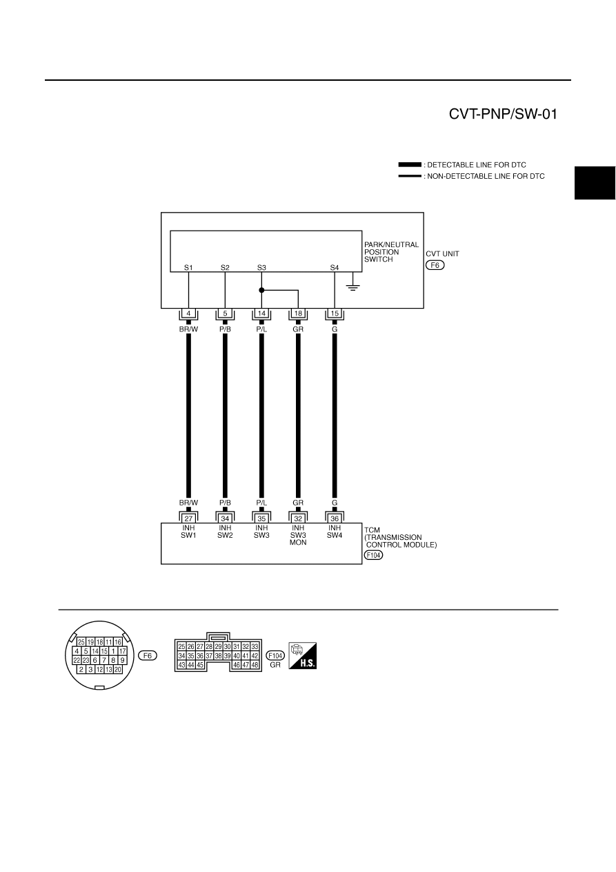
Wiring Diagram — CVT — PNP/SW

ACS001TV

TCWA0246E

CVT-86

DTC P0705 PARK/NEUTRAL POSITION SWITCH

Revision: 2005 August

2005 Murano

TCM terminal data are reference values, measured between each terminal and ground.

*: Without manual mode

Terminal

Wire color

Item

Condition

Data (Approx.)

27

BR/W

PNP switch 1

Selector lever in “P”, “L”* position.

Battery voltage

Selector lever in other position.

0V 

34

P/B

PNP switch 2

Selector lever in “P”, “R” position.

10.0V - Battery 
voltage

Selector lever in other position.

0V 

35

P/L

PNP switch 3

Selector lever in “P”, “R”, “N” position.

8.0V - Battery volt-
age

Selector lever in other position.

0V 

36

G

PNP switch 4

Selector lever in “P”, “N”, “L”* position.

10.0V - Battery 
voltage

Selector lever in other position.

0V 

32

GR

PNP switch 3 
(monitor)

Selector lever in “P”, “R”, “N” position.

8.0V - Battery volt-
age

Selector lever in other position.

0V 

DTC P0705 PARK/NEUTRAL POSITION SWITCH

CVT-87

D

E

F

G

H

I

J

K

L

M

A

B

CVT

Revision: 2005 August

2005 Murano

Diagnostic Procedure

ACS001TW

1. 

 CHECK PNP SW SIGNAL

 With CONSULT-II

1.

Turn ignition switch ON. (Do not start engine.)

2.

Select “ECU INPUT SIGNALS” in “DATA MONITOR” mode for
“TRANSMISSION” with CONSULT-II.

3.

Selector lever to “P”, “R”, “N”,“D”, “S”* and “L”* position to check
the value of “INH SW1” “INH SW2” “INH SW3” “INH SW4” and
“INH SW3M”.
*: Without manual mode

*: Without manual mode

 Without CONSULT-II

1.

Turn ignition switch ON. (Do not start engine.)

2.

Change selector lever to “P“, “R”, “N”, “D”, “S”* or “L”* position to
check voltage between the TCM connector terminals and
ground.
*: Without manual mode

*: Without manual mode

OK or NG

OK

>> GO TO 5.

NG

>> GO TO 2.

 Shift 

posi-

tion

 “INH SW1”

 “INH SW2”

 “INH SW3”

 “INH SW4”

 “INH SW3M”

 P

 OFF

 OFF

 OFF

 OFF

 OFF

 R

ON

 OFF

 OFF

ON

 OFF

 N

ON

ON

 OFF

 OFF

 OFF

 D · S*

ON

ON

ON

ON

ON

 L*

 OFF

ON

ON

 OFF

ON

SCIA2276E

Shift 

position

Connector

F104

Terminal (Wire color)

27 (BR/W) - 

Ground

34 (P/B) - 

Ground

35 (P/L) - 

Ground

36 (G) - 

Ground

 32 (GR) - 

Ground

P

Battery 
voltage

10.0V - Bat-

tery voltage

8.0V - Bat-

tery voltage

10.0V - 
Battery 
voltage

8.0V - Bat-

tery voltage

R

0V

10.0V - Bat-

tery voltage

8.0V - Bat-

tery voltage

0V

8.0V - Bat-

tery voltage

N

0V

0V

8.0V - Bat-

tery voltage

10.0V - 
Battery 
voltage

8.0V - Bat-

tery voltage

 D · S*

0V

0V

0V

0V

0V

L*

Battery 
voltage

0V

0V

10.0V - 
Battery 
voltage

0V

SCIA2024E

CVT-88

DTC P0705 PARK/NEUTRAL POSITION SWITCH

Revision: 2005 August

2005 Murano

2. 

 CHECK PNP SW CIRCUIT

1.

Turn ignition switch OFF.

2.

Disconnect TCM connector.

3.

Check continuity between TCM connector terminal and ground.

*: Without manual mode

4.

If OK, check harness for short-circuit to ground or power supply. 

OK or NG

OK

>> GO TO 5.

NG

>> GO TO 3.

Connector

Terminal

(Wire color)

Condition

Continuity

F104

27 (BR/W) - ground

Select lever in “P”, “L”* posi-
tion.

No

Select lever in other position.

Yes

34 (P/B) - ground

Select lever in “P”, “R” posi-
tion.

No

Select lever in other position.

Yes

35 (P/L) - ground

Select lever in “P”, “R”, “N” 
position.

No

Select lever in other position.

Yes

36 (G) - ground

Select lever in “P”,“N”, “L”* 
position.

No

Select lever in other position.

Yes

32 (GR) - ground

Select lever in “P”, “R”, “N” 
position.

No

Select lever in other position.

Yes

SCIA5258E

DTC P0705 PARK/NEUTRAL POSITION SWITCH

CVT-89

D

E

F

G

H

I

J

K

L

M

A

B

CVT

Revision: 2005 August

2005 Murano

3. 

 CHECK HARNESS BETWEEN TCM AND PNP SWITCH

1.

Turn ignition switch OFF.

2.

Disconnect TCM connector and CVT unit harness connector.

3.

Check continuity between TCM connector terminal and CVT unit
harness connector terminal.

4.

If OK, check harness for short to ground and short to power.

5.

Reinstall any part removed.

 OK or NG

 OK

>> GO TO 4.

 NG

>> Repair or replace damaged parts.

4. 

 DETECT MALFUNCTIONING ITEM

Check the following.

PNP switch. Refer to 

CVT-90, "Component Inspection"

 .

 OK or NG

 OK 

>> GO TO 5.

 NG

>> Repair or replace damaged parts.

5. 

CHECK DTC

Perform “DTC Confirmation Procedure”. Refer to 

CVT-83, "DTC Confirmation Procedure"

 .

OK or NG

OK >> INSPECTION END
NG

>> GO TO 6.

6. 

CHECK TCM

1.

Check TCM input/output signal. Refer to 

CVT-58, "TCM Input/Output Signal Reference Values"

 .

2.

If NG, re-check TCM pin terminals for damage or loose connection with harness connector.

OK or NG

OK

>> INSPECTION END

NG

>> 1. Repair or replace damaged parts.

2. Replace the transaxle assembly. Refer to 

CVT-232, "Removal and Installation"

 .

 Item

 Connector

 Terminal

(Wire color)

 Continuity

 TCM

 F104

27 (BR/W)

 Yes

 CVT unit harness connector

 F6

4 (BR/W)

 TCM

 F104

34 (P/B)

 Yes

 CVT unit harness connector

 F6

5 (P/B)

 TCM

 F104

35 (P/L)

 Yes

 CVT unit harness connector

 F6

14 (P/L)

 TCM

 F104

32 (GR)

 Yes

 CVT unit harness connector

 F6

18 (GR)

 TCM

 F104

36 (G)

 Yes

 CVT unit harness connector

 F6

15 (G)

SCIA3182E

CVT-90

DTC P0705 PARK/NEUTRAL POSITION SWITCH

Revision: 2005 August

2005 Murano

Component Inspection

ACS001TX

PNP SWITCH

1.

Change selector lever to various positions to check the continu-
ity between terminals on the PNP switch and ground.

*: Without manual mode

2.

If NG, check continuity with control cable disconnected. (Refer to step 1 above.)

3.

If OK, with the control cable disconnected, adjust the control linkage. Refer to 

CVT-214, "Adjustment of

CVT Position"

 .

4.

If NG, even when the control cable is disconnected, replace the transaxle assembly. Refer to 

CVT-232,

"Removal and Installation"

 .

PNP SW

Shift position

Connector

Terminal

Continuity

SW 1

“R”, “N”, “D”, “S”*

F6

4 - Ground

 Yes

 other position.

 No

SW 2

“N”, “D”, “S”*, “L”*

5 - Ground

 Yes

 other position.

 No

SW 3

“D”, “S”*, “L”*

14 - Ground

 Yes

 other position.

 No

SW 4

“R”, “D”, “S”*

15 - Ground

 Yes

 other position.

 No

SW 3 Moni-
tor

“D”, “S”*, “L”*

 18 - Ground

 Yes

 other position.

 No

SCIA4678E

DTC P0710 CVT FLUID TEMPERATURE SENSOR CIRCUIT

CVT-91

D

E

F

G

H

I

J

K

L

M

A

B

CVT

Revision: 2005 August

2005 Murano

DTC P0710 CVT FLUID TEMPERATURE SENSOR CIRCUIT

PFP:31020

Description

ACS002SN

The CVT fluid temperature sensor detects the CVT fluid temperature and sends a signal to the TCM.

CONSULT-II Reference Value

ACS002SO

Remarks: Specification data are reference values.

On Board Diagnosis Logic

ACS002SP

This is an OBD-II self-diagnostic item.

Diagnostic trouble code “P0710 ATF TEMP SEN/CIRC” with CONSULT-II is detected when TCM receives
an excessively low or high voltage from the sensor.

Possible Cause

ACS002SQ

Harness or connectors
(Sensor circuit is open or shorted.)

CVT fluid temperature sensor

DTC Confirmation Procedure

ACS002SR

CAUTION:

Always drive vehicle at a safe speed.

NOTE:
If “DTC Confirmation Procedure” has been previously performed, always turn ignition switch OFF and
wait at least 10 seconds before performing the next test.
 After the repair, touch “ERASE” on “SELF-DIAG RESULTS” and then perform the following procedure to con-
firm the malfunction is eliminated.

 WITH CONSULT-II

1.

Turn ignition switch ON. (Do not start engine.)

2.

Select “DATA MONITOR” mode for “TRANSMISSION” with
CONSULT-II.

3.

Start engine and maintain the following conditions for at least 10
minutes (Total).
VHCL SPEED SE: 10 km/h (6 MPH) or more
ENG SPEED: 450 rpm more than
ACC PEDAL OPEN: More than 1/8
Selector lever: “D” position

4.

If DTC is detected, go to 

CVT-93, "Diagnostic Procedure"

 .

 WITH GST

Follow the procedure “WITH CONSULT-II”.

 Monitor item

 Condition

Display value (Approx.)

ATF TEMP SEN

 Cold [20

°

C (68

°

F)]

1.8 - 2.0V

 Hot [80

°

C (176

°

F)]

0.6 - 1.0V

BCIA0031E

CVT-92

DTC P0710 CVT FLUID TEMPERATURE SENSOR CIRCUIT

Revision: 2005 August

2005 Murano

Wiring Diagram — CVT — FTS

ACS0020Q

TCWA0247E

DTC P0710 CVT FLUID TEMPERATURE SENSOR CIRCUIT

CVT-93

D

E

F

G

H

I

J

K

L

M

A

B

CVT

Revision: 2005 August

2005 Murano

TCM terminal data are reference values, measured between each terminal and ground.

Diagnostic Procedure

ACS002SS

1. 

 CHECK CVT FLUID TEMPERATURE SENSOR SIGNAL

 With CONSULT-II

1.

Start engine.

2.

Select “ECU INPUT SIGNALS” in “DATA MONITOR” mode for
“TRANSMISSION” with CONSULT-II.

3.

Read out the value of “ATF TEMP SEN”.

 Without CONSULT-II

1.

Start engine.

2.

Check voltage between TCM connector terminals.

3.

Turn ignition switch OFF.

4.

Disconnect TCM connector.

5.

Check if there is continuity between connector terminal and
ground.

OK or NG

OK >> GO 

TO 

5.

NG

>> GO TO 2.

2. 

 CHECK CVT FLUID TEMPERATURE SENSOR CIRCUIT

1.

Turn ignition switch OFF.

2.

Disconnect the TCM connector.

3.

Check resistance between TCM connector terminals.

OK or NG

OK

>> GO TO 5.

NG

>> GO TO 3.

Terminal

Wire color

Item

Condition

Data (Approx.)

42

W/R

Sensor ground

Always

0V

47

V

CVT fluid tempera-
ture sensor

When CVT fluid temperature is 20

°

(68

°

F).

2.0V

When CVT fluid temperature is 80

°

(176

°

F).

1.0V

 Monitor item

 Condition

Display value (Approx.)

ATF TEMP SEN

 Cold [20

°

C (68

°

F)]

1.8 - 2.0V

 Hot [80

°

C (176

°

F)]

0.6 - 1.0V

SCIA2277E

Name

Connector

 Terminal

 (Wire color)

Temperature 

°

C (

°

F)

Voltage 

(Approx.)

CVT fluid tem-
perature sen-
sor

 F104

47 (V) - 42 (W/R)

20 (68)

2.0V

80 (176)

1.0V

SCIA2027E

 Name

 Connector

 Terminal

 (Wire color)

 Temperature 

°

C (

°

F)

 Resistance 

(Approx.)

 CVT fluid tem-
perature sensor

 F104

 47 (V) - 42 (W/R)

 20 (68)

6.5 k

80 (176)

 0.9 k

SCIA2510E

CVT-94

DTC P0710 CVT FLUID TEMPERATURE SENSOR CIRCUIT

Revision: 2005 August

2005 Murano

3. 

 CHECK CVT FLUID TEMPERATURE SENSOR

1.

Turn ignition switch OFF.

2.

Disconnect CVT unit harness connector.

3.

Check resistance between CVT unit harness connector termi-
nals.

4.

Reinstall any part removed.

OK or NG

OK

>> GO TO 4.

NG

>> Replace the transaxle assembly. Refer to 

CVT-232,

"Removal and Installation"

 .

4. 

 CHECK HARNESS BETWEEN TCM AND CVT FLUID TEMPERATURE SENSOR

1.

Turn ignition switch OFF.

2.

Disconnect the TCM connector and CVT unit harness connector.

3.

Check continuity between TCM connector terminal and CVT unit
harness connector terminal.

4.

If OK, check harness for short to ground and short to power.

5.

Reinstall any part removed.

 OK or NG

 OK

>> GO TO 5.

 NG

>> Repair or replace damaged parts.

5. 

CHECK DTC

Perform “DTC Confirmation Procedure”. Refer to 

CVT-91, "DTC Confirmation Procedure"

 .

OK or NG

OK

>> INSPECTION END

NG

>> GO TO 6.

6. 

CHECK TCM

1.

Check TCM input/output signal. Refer to 

CVT-58, "TCM Input/Output Signal Reference Values"

 .

2.

If NG, re-check TCM pin terminals for damage or loose connection with harness connector.

OK or NG

OK

>> INSPECTION END

NG

>> Repair or replace damaged parts.

Name

Connector

Terminal

Tempera-

ture 

°

C (

°

F)

Resistance 

(Approx.)

CVT fluid 
tempera-
ture sensor

F6

17 - 19

20 (68)

6.5 k

80 (176)

 0.9 k

SCIA4679E

 Item

 Connector

 Terminal

(Wire color)

 Continuity

 TCM

 F104

 42 (W/R)

 Yes

 CVT unit harness connector

 F6

 19 (W/R)

 TCM

 F104

 47 (V)

 Yes

 CVT unit harness connector

 F6

 17 (V)

SCIA4680E

DTC P0710 CVT FLUID TEMPERATURE SENSOR CIRCUIT

CVT-95

D

E

F

G

H

I

J

K

L

M

A

B

CVT

Revision: 2005 August

2005 Murano

 Component Inspection

ACS003KY

 CVT FLUID TEMPERATURE SENSOR

1.

Turn ignition switch OFF.

2.

Disconnect CVT unit harness connector.

3.

Check resistance between CVT unit harness connector termi-
nals.

4.

If NG, replace the transaxle assembly. Refer to 

CVT-232,

"Removal and Installation"

 .

 Name

 Connector

 Terminal

 Tempera-

ture 

°

C (

°

F)

 Resistance 

(Approx.)

 CVT fluid 
tempera-
ture sensor

 F6

 17 - 19

 20 (68)

6.5 k

 80 (176)

 0.9 k

SCIA4679E

CVT-96

DTC P0715 INPUT SPEED SENSOR CIRCUIT (PRI SPEED SENSOR)

Revision: 2005 August

2005 Murano

DTC P0715 INPUT SPEED SENSOR CIRCUIT (PRI SPEED SENSOR)

PFP:31935

Description

ACS002ST

The input speed sensor (primary speed sensor) detects the primary pulley revolution speed and sends a sig-
nal to the TCM.

CONSULT-II Reference Value

ACS002SU

Remarks: Specification data are reference values.

On Board Diagnosis Logic

ACS002SV

This is an OBD-II self-diagnostic item.

Diagnostic trouble code “P0715 INPUT SPD SEN/CIRC” with CONSULT-II is detected when TCM does
not receive the proper signal from the sensor.

Possible Cause

ACS002SW

Harness or connectors
(Sensor circuit is open or shorted.)

Input speed sensor (Primary speed sensor)

DTC Confirmation Procedure

ACS002SX

CAUTION:

Always drive vehicle at a safe speed.

Be careful not to rev engine into the red zone on the tachometer.

NOTE:
If “DTC Confirmation Procedure” has been previously performed, always turn ignition switch OFF and
wait at least 5 seconds before performing the next test.
 After the repair, touch “ERASE” on “SELF-DIAG RESULTS” and then perform the following procedure to con-
firm the malfunction is eliminated.

 WITH CONSULT-II

1.

Turn ignition switch ON and select “DATA MONITOR” mode for
“TRANSMISSION” with CONSULT-II.

2.

Start engine and maintain the following conditions for at least 5
consecutive seconds.
VHCL SPEED SE: 10 km/h (6 MPH) or more
ACC PEDAL OPEN: More than 1/8
Selector lever: “D” position
ENG SPEED: 450 rpm or more
Driving location: Driving the vehicle uphill (increased
engine load) will help maintain the driving conditions
required for this test.

3.

If DTC is detected, go to 

CVT-98, "Diagnostic Procedure"

 .

 WITH GST

Follow the procedure “WITH CONSULT-II”.

Monitor item

Condition

Display value

 ENG SPEED SIG

Engine running

Closely matches the tachometer reading.

PRI SPEED SEN

During driving (lock-up ON)

Approximately matches the engine speed.

BCIA0031E

DTC P0715 INPUT SPEED SENSOR CIRCUIT (PRI SPEED SENSOR)

CVT-97

D

E

F

G

H

I

J

K

L

M

A

B

CVT

Revision: 2005 August

2005 Murano

Wiring Diagram — CVT — PRSCVT

ACS0020X

TCWA0254E

CVT-98

DTC P0715 INPUT SPEED SENSOR CIRCUIT (PRI SPEED SENSOR)

Revision: 2005 August

2005 Murano

TCM terminal data are reference values.

Diagnostic Procedure

ACS0020Y

1. 

CHECK INPUT SIGNAL

 With CONSULT-II

1.

Start engine.

2.

Select “ECU INPUT SIGNALS” in “DATA MONITOR” mode for
“TRANSMISSION” with CONSULT-II.

3.

Start vehicle and read out the value of “PRI SPEED SEN”.

OK or NG

OK

>> GO TO 6.

NG

>> GO TO 2.

2. 

CHECK INPUT SPEED SENSOR (PRIMARY SPEED SENSOR)

1.

Start engine.

2.

Check voltage between TCM connector terminals.

3.

Check the pulse with CONSULT-II or oscilloscope, when vehicle
cruises.

OK or NG

OK >> GO 

TO 

6.

 NG - 1 >> Battery voltage is not supplied: GO TO 3.
 NG - 2 >> Battery voltage is supplied, but there is a malfunction in

the frequency: GO TO 4.

Terminal

Wire color

Item

Condition

Data (Approx.)

38

LG

Input speed sensor 
(Primary speed sen-
sor)

When driving [“D” position, 20 km/h (12 
MPH)].

600 Hz

42

W/R

Sensor ground

Always

0V

46

L/O

Sensor power

 4.5 - 5.5V


0V

 Monitor item

 Condition

Display value

PRI SPEED SEN

During driving (lock-up 
ON)

Approximately matches 
the engine speed.

SCIA2278E

 Item

 Connector

 Terminal (Wire color)

 Data (Approx.) 

TCM

 F104

 46 (L/O) - 42 (W/R)

 4.5 - 5.5V

Name

Condition

Input speed sensor 
(Primary speed 
sensor)

When running at 20 km/h (12 MPH) in “D” position with the 
closed throttle position signal “OFF”, use the CONSULT-II 
pulse frequency measuring function.

CAUTION:

Connect the data link connector to the vehicle-side diag-
nosis connector.

Item

Connector

Terminal

(Wire color)

Name

Data 

(Approx.) 

TCM

F104

38 (LG)

Input speed sensor (Primary 
speed sensor)

 600 Hz

SCIA1915E

DTC P0715 INPUT SPEED SENSOR CIRCUIT (PRI SPEED SENSOR)

CVT-99

D

E

F

G

H

I

J

K

L

M

A

B

CVT

Revision: 2005 August

2005 Murano

3. 

 CHECK HARNESS BETWEEN TCM AND CVT UNIT HARNESS CONNECTOR (SENSOR POWER 

AND SENSOR GROUND)

1.

Turn ignition switch OFF.

2.

Disconnect TCM connector and CVT unit harness connector.

3.

Check continuity between TCM connector terminal and CVT unit
harness connector terminal.

4.

If OK, check harness for short to ground and short to power.

5.

Reinstall any part removed.

 OK or NG

 OK

>> GO TO 6.

 NG

>> Repair open circuit or short to ground or short to power in harness or connectors.

4. 

 CHECK HARNESS BETWEEN TCM AND CVT UNIT HARNESS CONNECTOR [INPUT SPEED SEN-

SOR (PRIMARY SPEED SENSOR)]

1.

Turn ignition switch OFF.

2.

Disconnect TCM connector and CVT unit harness connector.

3.

Check continuity between TCM connector terminal and CVT unit
harness connector terminal.

4.

If OK, check harness for short to ground and short to power.

5.

Reinstall any part removed.

 OK or NG

 OK

>> GO TO 5.

 NG

>> Repair open circuit or short to ground or short to power in harness or connectors.

5. 

 CHECK THE TCM SHORT

Replace same type TCM, perform self-diagnosis check. Erase self-diagnostic results and then drive the vehi-
cle [10 km/h (6 MPH) or more], perform self-diagnosis check. Refer to 

CVT-96, "DTC Confirmation Procedure"

.
 Is the “P0715 INPUT SPD SEN/CIRC” detected again?

 YES

>> Replace the transaxle assembly. Refer to 

CVT-232, "Removal and Installation"

 .

 NO

>> Replace TCM. Refer to 

CVT-9, "Precautions for TCM and CVT Assembly Replacement"

 .

6. 

CHECK DTC

Perform “DTC Confirmation Procedure”. Refer to 

CVT-96, "DTC Confirmation Procedure"

 .

OK or NG

OK

>> INSPECTION END

NG

>> GO TO 7.

 Item

 Connector

 Terminal

 (Wire color)

 Continuity

 TCM

 F104

 42 (W/R)

 Yes

 CVT unit harness connector

 F6

 19 (W/R)

 TCM

 F104

 46 (L/O)

 Yes

 CVT unit harness connector

 F6

 20 (L/O)

SCIA4681E

 Item

 Connector

 Terminal

 (Wire color)

 Continuity

 TCM

 F104

 38 (LG)

 Yes

 CVT unit harness connector

 F6

22 (LG)

SCIA4682E

CVT-100

DTC P0715 INPUT SPEED SENSOR CIRCUIT (PRI SPEED SENSOR)

Revision: 2005 August

2005 Murano

7. 

CHECK TCM

1.

Check TCM input/output signal. Refer to 

CVT-58, "TCM Input/Output Signal Reference Values"

 .

2.

If NG, re-check TCM pin terminals for damage or loose connection with harness connector.

OK or NG

OK

>> INSPECTION END

NG

>> Repair or replace damaged parts.


Content      ..     61      62      63      64     ..