Nissan Murano Z50 (2005 year). Manual - part 34
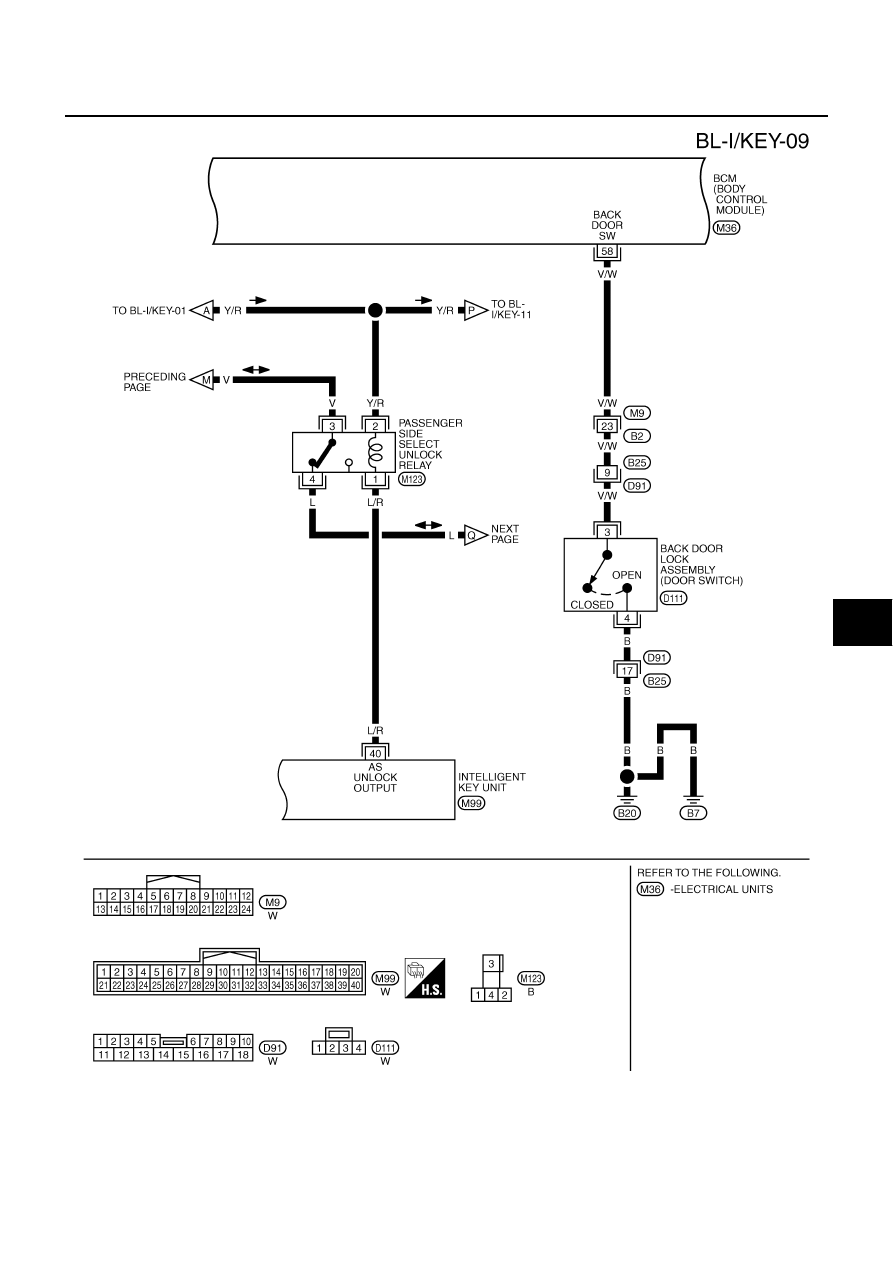
INTELLIGENT KEY SYSTEM
BL-113
C
D
E
F
G
H
J
K
L
M
A
B
BL
Revision: 2005 August
2005 Murano
TIWB0157E
|
|
|
INTELLIGENT KEY SYSTEM BL-113 C D E F G H J K L M A B BL Revision: 2005 August 2005 Murano TIWB0157E |