Nissan Murano Z50 (2005 year). Manual - part 31
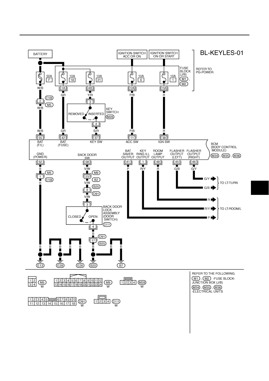
REMOTE KEYLESS ENTRY SYSTEM
BL-65
C
D
E
F
G
H
J
K
L
M
A
B
BL
Revision: 2005 August
2005 Murano
Wiring Diagram — KEYLES—
AIS002FJ
FIG. 1
TIWB0144E
|
|
|
REMOTE KEYLESS ENTRY SYSTEM BL-65 C D E F G H J K L M A B BL Revision: 2005 August 2005 Murano Wiring Diagram — KEYLES— AIS002FJ FIG. 1 TIWB0144E |