Nissan Murano Z50 (2005 year). Manual - part 30
POWER DOOR LOCK SYSTEM
BL-49
C
D
E
F
G
H
J
K
L
M
A
B
BL
Revision: 2005 August
2005 Murano
Check Key Switch
AIS003C6
1.
CHECK KEY SWITCH INPUT SIGNAL
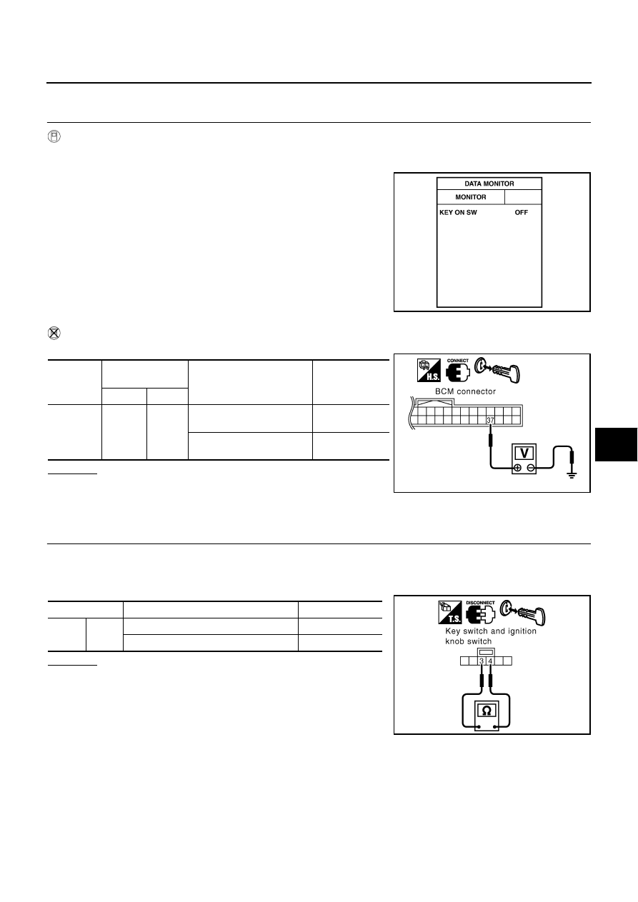
With CONSULT-II
Check ignition key switch “IGN ON SW” in “DATA MONITOR” mode with CONSULT-II.
●
When key is inserted in ignition key cylinder
●
When key is removed from ignition key cylinder
Without CONSULT-II
Check voltage between BCM connector and ground.
OK or NG
OK
>> Key switch circuit is OK.
NG
>> GO TO 2. (with Intelligent Key system)
NG
>> GO TO 3. (without Intelligent Key system)
2.
CHECK KEY SWITCH (WITH INTELLIGENT KEY SYSTEM)
1.
Turn ignition switch OFF.
2.
Disconnect key switch and ignition knob switch connector.
3.
Check continuity between key switch and ignition knob switch connector M118 terminals 3 and 4.
OK or NG
OK
>> Check the following
●
10A fuse [No.22, located in the fuse block (J/B)]
●
Harness for open or short between key switch and
ignition knob switch and fuse.
●
Harness for open short between BCM and key switch
and ignition knob switch.
NG
>> Replace key switch and ignition knob switch.
KEY ON SW
: ON
KEY ON SW
: OFF
PIIA6470E
Connector
Terminal
(Wire color)
Condition
Voltage [V]
(Approx.)
(+)
(–)
M34
37 (B/R)
Ground
Key is removed from ignition
key cylinder.
0
Key is inserted in ignition
key cylinder.
Battery voltage
PIIA6471E
Terminal
Condition
Continuity
3
4
Key is removed from ignition key cylinder.
No
Key is inserted in ignition key cylinder.
Yes
PIIA6140E