Nissan Murano Z50 (2005 year). Manual - part 21
NAVIGATION SYSTEM
AV-143
C
D
E
F
G
H
I
J
L
M
A
B
AV
Revision: 2005 August
2005 Murano
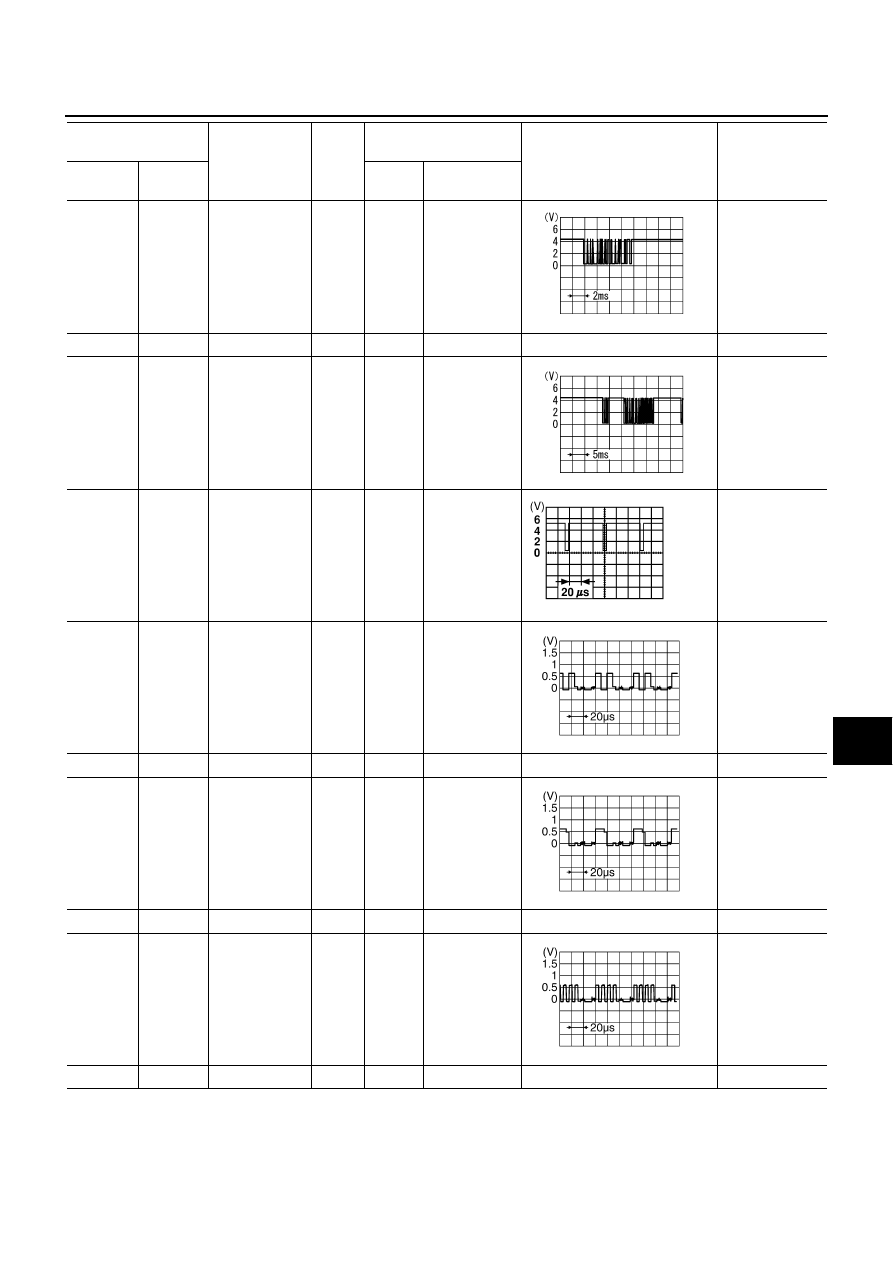
40 (R/G)
Ground
Communica-
tion signal
(Audio TX)
Output
ON
Operate audio
volume
Audio unit dose
not operate
properly.
41
Ground
Shield
—
ON
—
Approx. 0 V
—
42 (R/Y)
Ground
Communica-
tion signal
(Audio RX)
Input
ON
Operate audio
volume
Audio unit dose
not operate
properly.
43 (P/L)
41
RGB
synchronizing
signal
Input
ON
—
NAVI screen is
rolling.
44 (BR/Y)
45
RGB signal
(R: red)
Input
ON
Select “Dis-
play Diagno-
sis (NAVI)” of
CONFIRMA-
TION/
ADJUST-
MENT function
NAVI screen
looks bluish.
45
Ground
Shield
—
ON
—
Approx. 0 V
—
46
(BR/W)
45
RGB signal
(G: green)
Input
ON
Select “Dis-
play Diagno-
sis (NAVI)” of
CONFIRMA-
TION/
ADJUST-
MENT function
NAVI screen
looks reddish.
47
Ground
Shield
—
ON
—
Approx. 0 V
—
48 (BR)
45
RGB signal
(B: blue)
Input
ON
Select “Dis-
play Diagno-
sis (NAVI)” of
CONFIRMA-
TION/
ADJUST-
MENT function
NAVI screen
looks yellowish.
49
Ground
Shield
—
ON
—
Approx. 0 V
—
Terminal
(Wire color)
Item
Signal
input/
output
Condition
Reference value
Example of
symptom
+
–
Ignition
switch
Operation
SKIA4402E
SKIA4403E
SKIA0164E
SKIA4977E
SKIA4978E
SKIA4979E