Nissan Murano Z50 (2005 year). Manual - part 18
INTEGRATED DISPLAY SYSTEM
AV-95
C
D
E
F
G
H
I
J
L
M
A
B
AV
Revision: 2005 August
2005 Murano
Power Supply and Ground Circuit Check for Display Unit
AKS005FF
1.
CHECK FUSE
Make sure that the following fuses of the display unit are not blown.
OK or NG
OK
>> GO TO 2.
NG
>> If fuse is blown, be sure to eliminate cause of malfunction before installing new fuse. Refer to
3, "POWER SUPPLY ROUTING CIRCUIT"
.
2.
CHECK POWER SUPPLY CIRCUIT
Check voltage between display unit harness connector terminals
and ground.
OK or NG
OK
>> GO TO 3.
NG
>> Repair harness or connector.
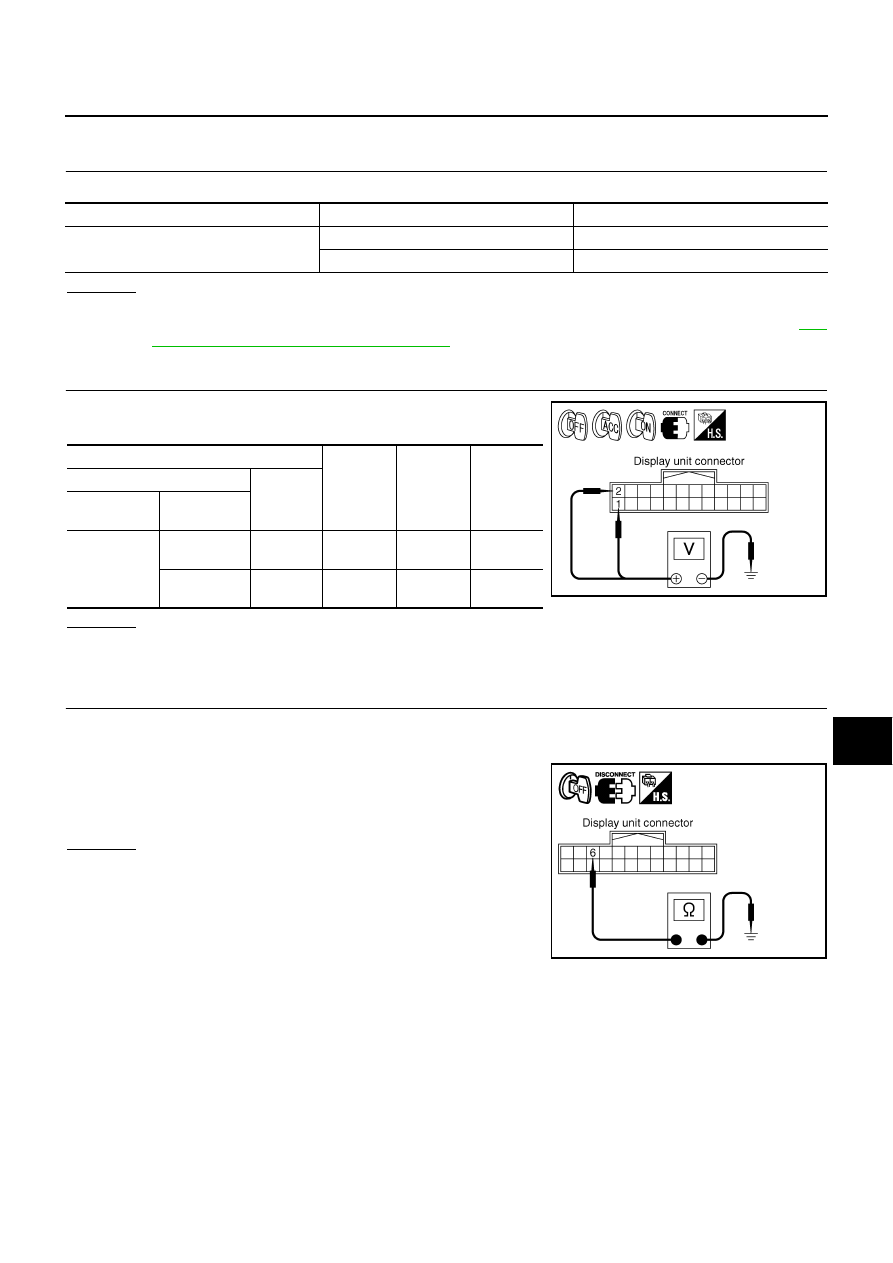
3.
CHECK GROUND CIRCUIT
1.
Turn ignition switch OFF.
2.
Disconnect display unit connector.
3.
Check continuity between display unit harness connector M39
terminal 6 (B) and ground.
OK or NG
OK
>> INSPECTION END
NG
>> Repair harness or connector.
Unit
Signal
Fuse No.
Display unit
Battery power supply
38
Ignition switch ACC or ON
6
Terminals
OFF
ACC
ON
(+)
(–)
Connector
Terminal
(Wire color)
M39
1 (Y)
Ground
Battery
voltage
Battery
voltage
Battery
voltage
2 (P/B)
Ground
0 V
Battery
voltage
Battery
voltage
SKIB0373E
6 – Ground
: Continuity should exist.
SKIA9483E