Nissan Murano Z50 (2005 year). Manual - part 5


  Index      Manuals     Nissan Murano Z50 (2005 year) - Service and Repair Manual


Search            copyright infringement  


Content      ..     3      4      5      6     ..


Nissan Murano Z50 (2005 year). Manual - part 5


TROUBLE DIAGNOSIS

ATC-41

C

D

E

F

G

H

I

K

L

M

A

B

ATC

Revision: 2005 August

2005 Murano

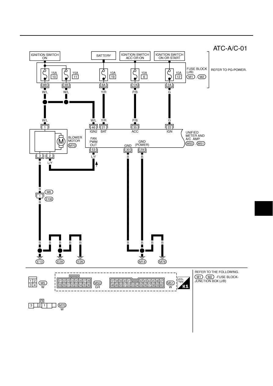
Wiring Diagram —A/C—

AJS000Z1

TJWB0091E

ATC-42

TROUBLE DIAGNOSIS

Revision: 2005 August

2005 Murano

TJWA0050E

TROUBLE DIAGNOSIS

ATC-43

C

D

E

F

G

H

I

K

L

M

A

B

ATC

Revision: 2005 August

2005 Murano

TJWA0096E

ATC-44

TROUBLE DIAGNOSIS

Revision: 2005 August

2005 Murano

TJWB0053E

TROUBLE DIAGNOSIS

ATC-45

C

D

E

F

G

H

I

K

L

M

A

B

ATC

Revision: 2005 August

2005 Murano

TJWB0054E

ATC-46

TROUBLE DIAGNOSIS

Revision: 2005 August

2005 Murano

Auto Amp. Terminals and Reference Value

AJS0010X

Measure voltage between each terminal and ground by referring ter-
minals and reference value for unified meter and A/C amp.

PIN CONNECTOR TERMINAL LAYOUT

TERMINALS AND REFERENCE VALUE FOR UNIFIED METER AND A/C AMP.

RJIA1758E

RJIA1759E

Terminal 

No.

Wire 

color

Item

Ignition 

switch

Condition

Voltage

(V)

1

L

CAN-H

11

Y

CAN-L

21

Y/R

Power supply for BAT

OFF

Battery voltage

22

G

Power supply for IGN

ON

Battery voltage

29

B

Ground (Power)

ON

Approx. 0

30

B

Ground

ON

Approx. 0

35

P/B

Power supply for ACC

ACC

Battery voltage

39

B/R

Ambient sensor

40

LG

In-vehicle sensor

41

R/Y

Intake sensor

42

GR

Compressor ON signal

ON

A/C switch: ON
(Blower motor operates.)

Approx. 0

OFF switch: ON
(A/C system: OFF)

Approx. 5

43

L/B

A/C LAN signal

ON

46

W/L

Power supply for IGN2

ON

Battery voltage

49

B/Y

Sensor ground

ON

Approx. 0

50

O

Sunload sensor

HAK0652D

TROUBLE DIAGNOSIS

ATC-47

C

D

E

F

G

H

I

K

L

M

A

B

ATC

Revision: 2005 August

2005 Murano

53

L/Y

Blower motor control signal

ON

Blower speed: 1st. step

54

L/W

Power supply for each door 
motor

ON

Battery voltage

57

SB

Blower motor ON signal

ON

A/C switch: ON
 (Blower motor operates.)

Approx. 0

OFF switch: ON
(A/C system: OFF)

Approx. 5

Terminal 

No.

Wire 

color

Item

Ignition 

switch

Condition

Voltage

(V)

SJIA0116J

ATC-48

TROUBLE DIAGNOSIS

Revision: 2005 August

2005 Murano

Self-diagnosis Function

AJS000Z3

DESCRIPTION

The self-diagnosis system diagnoses sensors, door motors, blower motor, etc. by system line. Refer to appli-
cable sections (items) for details. Shifting from usual control to the self-diagnosis system is accomplished by
starting the engine (turning the ignition switch ON) and pressing OFF switch for at least 5 seconds. The OFF
switch must be pressed within 10 seconds after starting the engine (ignition switch is turned ON). This system
will be canceled by either pressing AUTO switch or turning the ignition switch OFF. Shifting from one step to
another is accomplished by means of turning temperature control dial (driver side), as required.
Shifting from STEP-5 to AUXILIARY MECHANISM is accomplished by means of turning   (fan) control dial
clockwise.

SJIA0522E

TROUBLE DIAGNOSIS

ATC-49

C

D

E

F

G

H

I

K

L

M

A

B

ATC

Revision: 2005 August

2005 Murano

FUNCTION CONFIRMATION PROCEDURE

1. 

SET IN SELF-DIAGNOSIS MODE

1.

Turn ignition switch ON.

2.

Set in self-diagnosis mode as follows. Within 10 seconds after starting engine (ignition switch is turned
ON.), press OFF switch for at least 5 seconds.

CAUTION:

If battery voltage drops below 12 V during diagnosis STEP-3, door motor speed becomes slower
and as a result, the system may generate an error even when operation is normal. To avoid this,
start engine before performing this diagnosis.

Former STEP-1 (LEDs and display screen are checked) does not exist in this self-diagnosis func-
tion.

>> GO TO 2.

2. 

STEP-2: SENSOR CIRCUITS ARE CHECKED FOR OPEN OR SHORT CIRCUIT

Does code No. 20 appear on the display?

YES

>> GO TO 3.

NO

>> GO TO 13.

3. 

CHECK TO ADVANCE SELF-DIAGNOSIS STEP-3

Turn temperature control dial (driver side) clockwise.

Advance to self-diagnosis STEP-3?

YES

>> GO TO 4.

NO

>> Replace A/C and AV switch. (temperature control dial is malfunctioning.)

4. 

CHECK TO RETURN SELF-DIAGNOSIS STEP-2

Turn temperature control dial (driver side) counterclockwise.

Return to self-diagnosis STEP-2?

YES

>> GO TO 5.

NO

>> Replace A/C and AV switch. (temperature control dial is malfunctioning.)

5. 

STEP-3: MODE DOOR AND INTAKE DOOR POSITIONS ARE CHECKED

Turn temperature control dial (driver side) clockwise.
Does code No. 30 appear on the display?

YES

>> GO TO 6.

NO

>> GO TO 14.

RHA970DB

RHA869DD

ATC-50

TROUBLE DIAGNOSIS

Revision: 2005 August

2005 Murano

6. 

STEP-4: OPERATION OF EACH ACTUATOR IS CHECKED

1.

Turn temperature control dial (driver side) clockwise.

2.

Press 

 (DEF) switch. Code No. of each actuator test is indi-

cated on the display.

>> GO TO 7.

7. 

CHECK ACTUATORS

Refer to the following chart and confirm discharge air flow, air tem-
perature, blower motor duty ratio and compressor operation.

Checks must be made visually, by listening to any noise, or by touching air outlets with hand, etc. for improper
operation.
*1: FOOT position during automatic control. Refer to 

ATC-55, "AUXILIARY MECHANISM: FOOT POSITION

SETTING TRIMMER"

 .

OK or NG

OK

>> GO TO 8.

NG

>>

Air outlet does not change.
Go to Mode Door Motor Circuit. Refer to 

ATC-65, "Mode Door Motor Circuit"

 .

Intake door does not change.
Go to Intake Door Motor Circuit. Refer to 

ATC-71, "Intake Door Motor Circuit"

 .

Blower motor operation is malfunctioning.
Go to Blower Motor Circuit. Refer to 

ATC-74, "Blower Motor Circuit"

 .

Magnet clutch does not engage.
Go to Magnet Clutch Circuit. Refer to 

ATC-79, "Magnet Clutch Circuit"

 .

Discharge air temperature does not change.
Go to Air Mix Door Motor Circuit. Refer to 

ATC-68, "Air Mix Door Motor Circuit"

 .

RHA495A

RJIA3995E

Code No.

41

42

43

44

45

46

Mode door position

VENT

B/L 1

B/L 2

FOOT

*1

D/F

DEF

Intake door position

REC

REC

20%FRE

FRE

FRE

FRE

Air mix door position

FULL COLD

FULL COLD

FULL HOT

FULL HOT

FULL HOT

FULL HOT

Blower motor duty ratio

37%

91%

65%

65%

65%

91%

Compressor

ON

ON

OFF

OFF

ON

ON

TROUBLE DIAGNOSIS

ATC-51

C

D

E

F

G

H

I

K

L

M

A

B

ATC

Revision: 2005 August

2005 Murano

8. 

STEP-5: TEMPERATURE OF EACH SENSOR IS CHECKED

1.

Turn temperature control dial (driver side) clockwise.

2.

Code No. 51 appears on the display.

>> GO TO 9.

9. 

CHECK AMBIENT SENSOR

Press 

 (DEF) switch one time. Temperature detected by ambient

sensor is indicated on the display.

NOTE:
If temperature shown on display greatly differs from actual tempera-
ture, check sensor circuit first, and then inspect sensor.

OK or NG

OK

>> GO TO 10.

NG

>> Go to Ambient Sensor Circuit. Refer to 

ATC-97, "Ambi-

ent Sensor Circuit"

 .

10. 

CHECK IN-VEHICLE SENSOR

Press 

 (DEF) switch a second time. Temperature detected by in-

vehicle sensor is indicated on the display.

NOTE:
If temperature shown on display greatly differs from actual tempera-
ture, check sensor circuit first, and then inspect sensor.

OK or NG

OK

>> GO TO 11.

NG

>> Go to In-vehicle Sensor Circuit. Refer to 

ATC-100, "In-

vehicle Sensor Circuit"

 .

11. 

CHECK INTAKE SENSOR

Press 

 (DEF) switch a third time. Temperature detected by intake

sensor is indicated on the display.

NOTE:
If temperature shown on display greatly differs from actual tempera-
ture, check sensor circuit first, and then inspect sensor.
OK or NG

OK

>> GO TO 12.

NG

>> Go to Intake Sensor Circuit. Refer to 

ATC-106, "Intake

Sensor Circuit"

 .

RHA499G

RHA500G

RHA500GB

ATC-52

TROUBLE DIAGNOSIS

Revision: 2005 August

2005 Murano

12. 

CHECK CAN COMMUNICATION ERROR

1.

Press

(REC) switch.

2.

CAN communication error between unified meter and A/C amp.
and display unit or display control unit is detected.

OK or NG

OK

>> 1. Turn ignition switch OFF or AUTO switch ON.

2. INSPECTION END

NG

>> Go to CAN communication. Refer to 

DI-29, "CAN Com-

munication System Description"

 .

Unified meter and A/C amp. - Display unit

Unified meter and A/C amp. - Display control unit

13. 

CHECK MALFUNCTIONING SENSOR

Refer to the following chart for malfunctioning code No.
(If two or more sensors malfunction, corresponding code Nos. blink respectively twice.)
*1: Perform self-diagnosis STEP-2 under sunshine.
When performing indoors, aim a light (more than 60 W) at sunload sensor, otherwise code No. 25 will indicate
despite that sunload sensor is functioning properly.

*2

ATC-97, "DIAGNOSIS PROCEDURE FOR AMBIENT SENSOR"

 .

*3

ATC-101, "DIAGNOSIS PROCEDURE FOR IN-VEHICLE SENSOR"

 .

*4

ATC-106, "DIAGNOSIS PROCEDURE FOR INTAKE SENSOR"

 .

*5

ATC-103, "DIAGNOSIS PROCEDURE FOR SUNLOAD SENSOR"

 .

*6

ATC-61, "DIAGNOSIS PROCEDURE FOR LAN CIRCUIT"

 .

>> INSPECTION END

RJIA1762E

Code No.

Malfunctioning sensor (Including circuits)

Reference page

21 / 

21

Ambient sensor

*2

22 / 

22

In-vehicle sensor

*3

24 / 

24

Intake sensor

*4

25 / 

25

Sunload sensor 

*1

*5

26 / 

26

Air mix door motor PBR (Driver side)

*6

27 / 

27

Air mix door motor PBR (Passenger side)

RJIA0493E

TROUBLE DIAGNOSIS

ATC-53

C

D

E

F

G

H

I

K

L

M

A

B

ATC

Revision: 2005 August

2005 Murano

14. 

CHECK MALFUNCTIONING DOOR MOTOR POSITION SWITCH

Mode and/or intake door motor PBR(s) is/are malfunctioning.

(If two or more mode or intake doors are out of order, corresponding code numbers blink respectively twice.)
*1: If mode door motor harness connector is disconnected, the following display pattern will appear.
31

32

33

34

35

36

Return to 31

*2: If intake door motor harness connector is disconnected, the following display pattern will appear.
37

38

39

Return to 37

*3: FOOT position during automatic control. Refer to 

ATC-55, "AUXILIARY MECHANISM: FOOT POSITION

SETTING TRIMMER"

 .

*4: 

ATC-67, "DIAGNOSIS PROCEDURE FOR MODE DOOR MOTOR"

 .

*5: 

ATC-73, "DIAGNOSIS PROCEDURE FOR INTAKE DOOR MOTOR"

 .

>> INSPECTION END

Code No. 

*1*2

Mode or intake door position

Reference page

31

VENT

Mode door motor

*4

32

B/L 1

33

B/L 2

34

FOOT

*3

35

D/F

36

DEF

37

FRE

Intake door motor

*5

38

20% FRE

39

REC

RJIA0494E

ATC-54

TROUBLE DIAGNOSIS

Revision: 2005 August

2005 Murano

AUXILIARY MECHANISM: TEMPERATURE SETTING TRIMMER

The trimmer compensates for differences in range of 

±

3

°

C (

±

6

°

F) between temperature setting (displayed dig-

itally) and temperature felt by customer.
Operating procedures for this trimmer are as follows:

1.

Begin self-diagnosis STEP-5 mode. Refer to 

ATC-48, "Self-diagnosis Function"

 .

2.

Turn fan control dial clockwise to set system in auxiliary mode.

3.

Display shows 61 in auxiliary mechanism. It takes approximately 3 seconds.

4.

Turn temperature control dial (driver side) as desired. Temperature will change at a rate of 0.5

°

C (1.0

°

F)

each time a dial is turned.

CAUTION:

A decimal point is not indicated when the display shows “

°

C”.

When battery cable is disconnected, trimmer operation is canceled. Temperature set becomes that of initial
condition, i.e. 0

°

C (0

°

F).

SJIA0523E

TROUBLE DIAGNOSIS

ATC-55

C

D

E

F

G

H

I

K

L

M

A

B

ATC

Revision: 2005 August

2005 Murano

AUXILIARY MECHANISM: FOOT POSITION SETTING TRIMMER

Wind distribution ratio in FOOT mode can be set.
Operating procedures for this trimmer are as follows:
1.

Begin self-diagnosis STEP-5 mode. Refer to 

ATC-48, "Self-diagnosis Function"

 .

2.

Turn fan control dial clockwise to set system in auxiliary mode.

3.

Display shows 61 in auxiliary mechanism. It takes approximately 3 seconds.

4.

Press the mode switch as desired.

AUXILIARY MECHANISM: INLET PORT MEMORY FUNCTION

When ignition switch is turned from OFF to ON, inlet port can be set to AUTO or manual.
Operating procedures for this trimmer are as follows:
1.

Begin self-diagnosis STEP-5 mode. Refer to 

ATC-48, "Self-diagnosis Function"

 .

2.

Turn fan control dial clockwise to set system in auxiliary mode.

3.

Display shows 61 in auxiliary mechanism. It takes approximately 3 seconds.

4.

Press the recirculation (REC) and fresh (FRE) switch as desired.

RJIA3994E

 Switch

LED status of 

REC/FRE 

switch

Setting status

Setting changeover method

REC

ON

Manual REC status is memorized. (Initial setting)

REC SW: ON

OFF

AUTO control

FRE

ON

Manual FRE status is memorized. 

FRE SW: ON

OFF

AUTO control (Initial setting)

ATC-56

TROUBLE DIAGNOSIS

Revision: 2005 August

2005 Murano

Operational Check

AJS000Z4

The purpose of the operational check is to check if the individual system operates properly.

CHECKING MEMORY FUNCTION

1.

Turn temperature control dial clockwise until 32

°

C (90

°

F) is dis-

played.

2.

Press OFF switch.

3.

Turn ignition switch OFF.

4.

Turn ignition switch ON.

5.

Press the AUTO switch.

6.

Confirm that the set temperature remains at previous tempera-
ture.

7.

Press OFF switch.

If NG, go to trouble diagnosis procedure for 

ATC-96, "Memory Func-

tion"

 .

If OK, continue the check.

CHECKING BLOWER

1.

Turn fan control dial clockwise. Blower should operate on low
speed.

2.

Turn fan control dial clockwise again, and continue checking
blower speed and fan symbol until all speeds are checked.

3.

Leave blower on max. speed. 

If NG, go to trouble diagnosis procedure for 

ATC-76, "DIAGNOSIS

PROCEDURE FOR BLOWER MOTOR"

 .

If OK, continue the check.

CHECKING DISCHARGE AIR

1.

Press MODE switch and DEF switch.

2.

Each position indicator should change shape.

3.

Confirm that discharge air comes out according to the air distri-
bution table. Refer to 

ATC-32, "Discharge Air Flow"

 .

If NG, go to trouble diagnosis procedure for 

ATC-65, "Mode Door

Motor Circuit"

 .

If OK, continue the check.

NOTE:
Confirm that the compressor clutch is engaged (sound or visual
inspection) and intake door position is at FRESH when the DEF or
D/F is selected.

Conditions

: Engine running at normal operating temperature

RJIA1765E

RJIA1766E

RJIA1767E

RJIA3995E


Content      ..     3      4      5      6     ..