Nissan Murano Z50 (2004 year). Manual - part 220
TRANSFER ASSEMBLY
TF-63
C
E
F
G
H
I
J
K
L
M
A
B
TF
Revision: 2004 November
2004 Murano
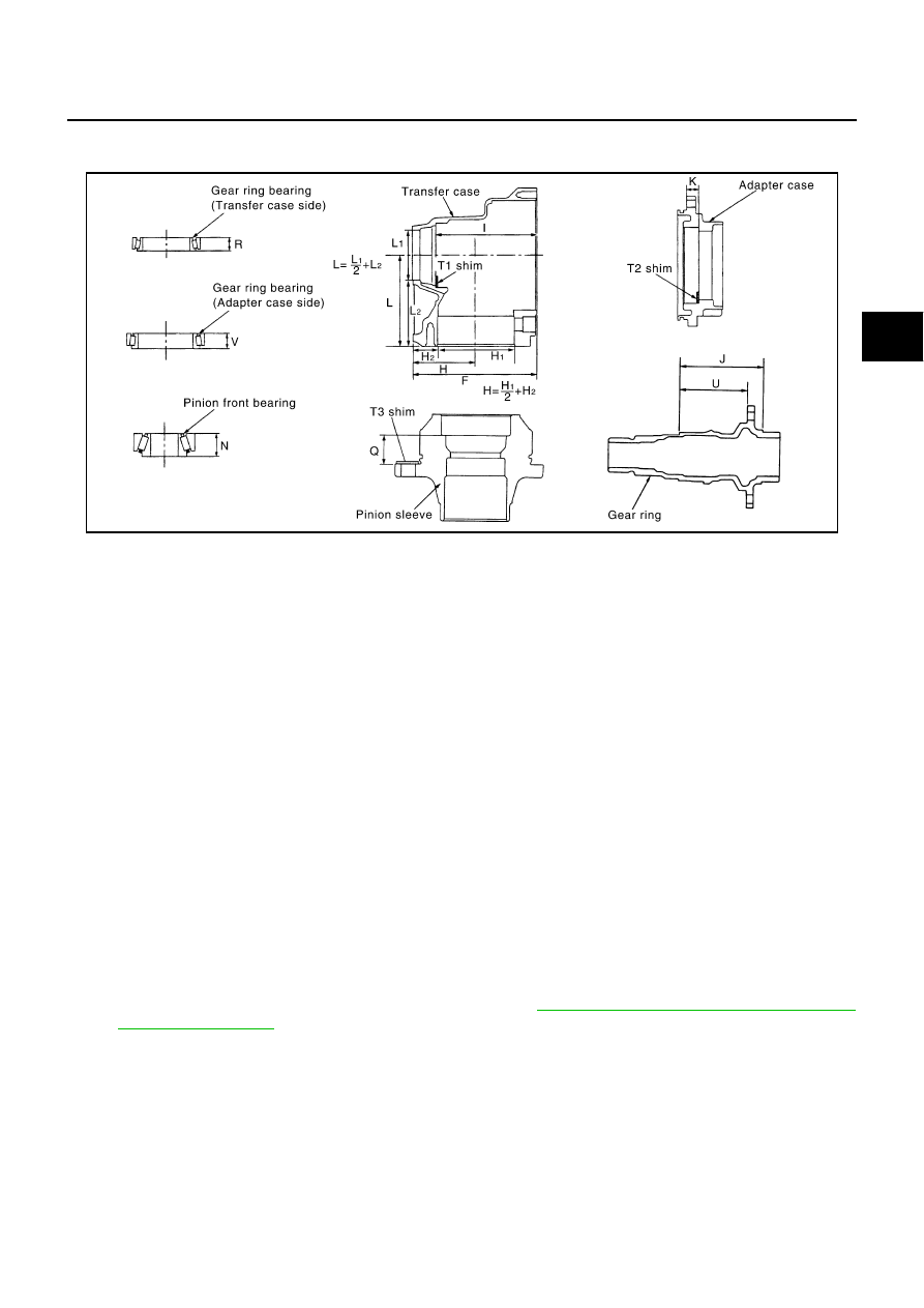
SELECTING ADJUSTING SHIMS
Measurement points
Gear Ring Bearing Adjusting Shim (Transfer Case Side)
1.
Measure the points F, H, I, R and U shown in the measurement points.
2.
Convert the values F, H, I, R and U according to the standards below.
3.
Check dimension Z on the drive gear side face.
NOTE:
Dimension Z indicates the difference between the optimum engagement and the standard dimensions in
increments of 0.01mm (0.0004 in) written on the drive gear side face.
4.
Use the formula below to calculate gear ring bearing adjusting shim (transfer case side) thickness T
1
.
5.
Select the gear ring bearing adjusting shim (transfer case side).
●
For information on selecting an adjusting shim, refer to
TF-70, "Gear Ring Bearing Adjusting Shim
CAUTION:
●
Only one adjusting shim can be selected.
●
If no adjusting shim with the calculated value is available, select the thicker and closest one.
Gear Ring Bearing Adjusting Shim (Adapter Case Side)
1.
Measure the points F, H, J, K, U and V shown in the measurement points.
2.
Convert the values F, H, J, K, U and V according to the standards below.
SDIA1179E
F:
Value obtained by subtracting 163.00 mm (6.42 in) from
the reading [in increments of 0.01 mm (0.0004 in)].
H:
Value obtained by subtracting 83.00 mm (3.27 in) from
the reading [in increments of 0.01 mm (0.0004 in)].
I:
Value obtained by subtracting 131.90 mm (5.19 in) from
the reading [in increments of 0.01 mm (0.0004 in)].
R:
Value obtained by subtracting 17.00 mm (0.67 in) from
the reading [in increments of 0.01 mm (0.0004 in)].
U:
Value obtained by subtracting 89.50 mm (3.524 in) from
the reading [in increments of 0.01 mm (0.0004 in)].
T
1
= (I - F + H + Z - U - R)
×
0.01 mm (0.0004 in) + 1.49 mm (0.0587 in)