Nissan Murano Z50 (2004 year). Manual - part 207


  Index      Manuals     Nissan Murano Z50 (2004 year) - Service and Repair Manual


Search            copyright infringement  


Content      ..     205      206      207      208     ..


Nissan Murano Z50 (2004 year). Manual - part 207


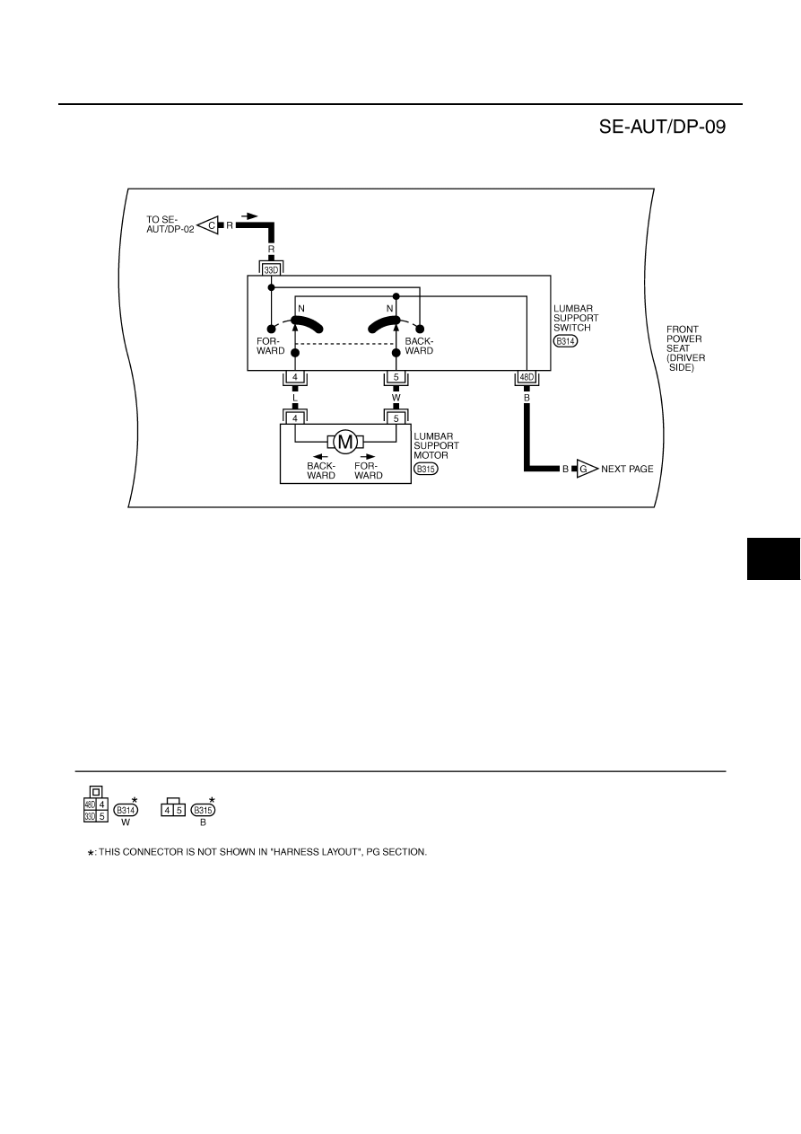
AUTOMATIC DRIVE POSITIONER

SE-29

C

D

E

F

G

H

J

K

L

M

A

B

SE

Revision: 2004 November

2004 Murano

TIWA0525E

SE-30

AUTOMATIC DRIVE POSITIONER

Revision: 2004 November

2004 Murano

TIWA0526E

AUTOMATIC DRIVE POSITIONER

SE-31

C

D

E

F

G

H

J

K

L

M

A

B

SE

Revision: 2004 November

2004 Murano

TIWA0527E

SE-32

AUTOMATIC DRIVE POSITIONER

Revision: 2004 November

2004 Murano

TIWA0528E

AUTOMATIC DRIVE POSITIONER

SE-33

C

D

E

F

G

H

J

K

L

M

A

B

SE

Revision: 2004 November

2004 Murano

Terminals and Reference Values for BCM

AIS003GI

Terminals and Reference Values for Driver Seat Control Unit

AIS003GJ

TERMINAL 

WIRE 

COLOR

ITEM

CONDITION

VOLTAGE (V)

(Approx)

11

P/B

Ignition switch ACC power supply

Ignition switch 
 (ACC or ON position)

Battery voltage

37

B/R

Key switch and key lock solenoid 

Key switch ON (key is inserted in 
ignition key cylinder)

Battery voltage 

Key switch OFF (key is removed 
from ignition key cylinder)

0

38

R

Ignition switch ON power supply

Ignition switch 
(ON or START position)

Battery voltage

39

L

CAN-H

40

Y

CAN-L

42

GR

Power source (Fuse)

Battery voltage

49

B

Ground (Signal)

0

52

B

Ground (Power)

0

55

W/B

Power source (Fusible link)

Battery voltage

62

SB

Drive side door switch

ON (Open) 

 OFF (Closed) 

 Battery voltage

TERMINAL

WIRE

COLOR

ITEM

CONDITION

VOLTAGE (V)

(Approx)

1

Y/W

UART LINE (RX)

Pedal adjusting switch ON (FR or 
RR operation)

3

L/Y

CAN-H

6

Y/G

Ignition switch START power 
supply

Ignition switch (START position)

Battery voltage

9

L

Reclining sensor signal

ON (seat reclining motor opera-
tion)

Other than above

0 or 5

10

W/R

Rear lifting sensor signal

ON (rear lifting motor operation)

Other than above

0 or 5

11

W/V

Sliding switch backward signal

ON (seat sliding switch backward 
operation)

0

OFF

Battery voltage

PIIA4813E

SIIA0692J

SIIA0693J

SE-34

AUTOMATIC DRIVE POSITIONER

Revision: 2004 November

2004 Murano

12

G/Y

Reclining switch backward sig-
nal

ON (seat reclining switch back-
ward operation)

0

OFF

Battery voltage

13

O/B

Front lifting switch DOWN signal

ON (front lifting switch DOWN 
operation)

0

OFF

Battery voltage

14

Y/R

Rear lifting switch DOWN signal

ON (rear lifting switch DOWN 
operation)

0

OFF

Battery voltage

15

G/R

Pedal adjusting switch backward 
signal

ON (pedal adjusting switch back-
ward operation)

 0

OFF

Battery voltage

17

Y/L

UART LINE (TX)

Pedal adjusting switch ON (FR or 
RR operation)

1

19

BR/W

CAN-L

21

R/L

Detention switch signal

Selector lever P position
With ignition key in ignitoin key 
cylinder

0

Selector lever other than P posi-
tion
With ignition key in ignition key 
cylinder

Battery voltage

24

G/B

Seat sliding sensor signal

ON (seat sliding motor operation)

Other than above

0 or 5

25

Y/B

Front lifting sensor signal

ON (front lifting motor operation)

Other than above

0 or 5

26

G/W

Seat sliding switch forward sig-
nal

ON (seat sliding switch forward 
operation)

0

OFF

Battery voltage

27

L/W

Seat reclining switch forward 
signal

ON (seat reclining switch forward 
operation)

0

OFF

Battery voltage

TERMINAL

WIRE

COLOR

ITEM

CONDITION

VOLTAGE (V)

(Approx)

PIIA4814E

PIIA3277E

SIIA0691J

AUTOMATIC DRIVE POSITIONER

SE-35

C

D

E

F

G

H

J

K

L

M

A

B

SE

Revision: 2004 November

2004 Murano

Terminals and Reference Values for Automatic Driver Positioner Control Unit

AIS003GK

28

L/R

Front lifting switch UP signal

ON (front lifting switch UP opera-
tion)

0

OFF

Battery voltage

29

W/G

Rear lifting switch UP signal

ON (rear lifting switch UP opera-
tion)

0

OFF

Battery voltage

30

W/L

Pedal adjusting switch forward 
signal

ON (pedal adjusting switch for-
ward operation)

0

OFF

Battery voltage

31

R/W

Sensor ground

0

32

B/W

Ground (Signal)

0

33

R

Power source (Fucible link)

Battery voltage

35

W

Sliding motor forward output sig-
nal

Sliding switch forward operation 
(Motor operated)

Battery voltage

OFF

0

36

G

Reclining motor forward output 
signal

Reclining switch forward operation 
(Motor operated)

Battery voltage

OFF

0

37

V

Front lifting motor DOWN output 
signal

Front lifting switch down operation 
(Motor operated)

Battery voltage

OFF

0

38

L

Rear lifting motor UP output sig-
nal

Rear end lifting switch up opera-
tion (Motor operated)

Battery voltage

OFF

39

Y

Rear lifting motor DOWN output 
signal

Rear end lifting switch down oper-
ation (Motor operated)

Battery voltage

OFF

0

40

W/B

Power source (Fuse)

Battery voltage

42

BR

Sliding motor backward output 
signal

Sliding switch backward opera-
tion (Motor operated)

Battery voltage

OFF

0

44

LG

Reclining motor backward out-
put signal

Reclining switch backward opera-
tion (Motor operated)

Battery voltage

OFF

0

45

O

Front lifting motor UP output sig-
nal

Front lifting switch upward opera-
tion (Motor operated)

Battery voltage

OFF

 0 

48

B

Ground (Power)

 0

TERMINAL

WIRE

COLOR

ITEM

CONDITION

VOLTAGE (V)

(Approx)

TERMINAL 

WIRE 

COLOR

ITEM

CONDITION

VOLTAGE (V)

(Approx)

2

L/W

Changeover switch RH signal

When changeover switch in RH 
position

0

When changeover switch in neutral 
position

5

SE-36

AUTOMATIC DRIVE POSITIONER

Revision: 2004 November

2004 Murano

3

Y/B

Mirror switch UP signal

When mirror switch in UP position

0

When mirror switch in neutral posi-
tion

5

4

V/W

Mirror switch LEFT signal

When mirror switch in LEFT position

0

When mirror switch in neutral posi-
tion

5

5

R/B

Mirror sensor (RH vertical) sig-
nal

When mirror motor RH is UP or 
DOWN operation

Changes between 3.4 (close to 
perk) 0.6 (close to valley)

6

L/Y

Mirror sensor (LH vertical) sig-
nal

When mirror motor LH is UP or 
DOWN operation

Changes between 3.4 (close to 
perk) 0.6 (close to valley)

8

P/B

Pedal sensor input signal

Pedal position front end

0.5

Pedal position rear end

4.5

9

LG/B

Power seat memory switch 1 
signal

Memory switch 1 ON

0

Memory switch 1 OFF

5

10

R

UART LINE (TX)

Pedal adjusting switch ON (FR or 
RR operation)

12

GR/L

Power seat memory switch 
indictor 1 signal

Memory switch 1 ON

1

Memory switch 1 OFF

Battery voltage

13

Y/G

Power seat memory switch 
indictor 2 signal

Memory switch 2 ON

1

Memory switch 2 OFF

Battery voltage

14

GR/R

Mirror motor RH UP signal

When mirror motor RH UP opera-
tion

1.5 - Battery voltage

Mirror motor RH OFF

0

15

LG

Mirror motor RH LEFT signal

When mirror motor RH LEFT opera-
tion

1.5 - Battery voltage

Mirror motor RH OFF

0

16

LG/R

Mirror motor LH DOWN signal

When mirror motor LH DOWN oper-
ation

1.5 - Battery voltage

Mirror motor LH OFF

0

Mirror motor LH RIGHT signal

When mirror motor LH RIGHT oper-
ation

1.5 - Battery voltage

Mirror motor LH OFF

0

18

BR/Y

Changeover switch LH signal

When changeover switch in LH 
position

0

When changeover switch in neutral 
position

5

19

L/O

Mirror switch DOWN signal

When mirror switch in DOWN posi-
tion

0

When mirror switch in neutral posi-
tion

5

20

V

Mirror switch RIGHT signal

When mirror switch in RIGHT posi-
tion

0

When mirror switch in neutral posi-
tion

5

TERMINAL 

WIRE 

COLOR

ITEM

CONDITION

VOLTAGE (V)

(Approx)

PIIA4813E

AUTOMATIC DRIVE POSITIONER

SE-37

C

D

E

F

G

H

J

K

L

M

A

B

SE

Revision: 2004 November

2004 Murano

21

L

Mirror sensor (RH horizontal) 
signal

When mirror motor RH is LEFT or 
RIGHT operation

Changes between 3.4 (close to left 
edge) 0.6 (close to right edge)

22

G

Mirror sensor (LH horizontal) 
signal

When mirror motor LH is LEFT or 
RIGHT operation

Changes between 3.4 (close to left 
edge) 0.6 (close to right edge)

24

R/Y

Power seat set switch signal

Set switch 1 ON

0

Set switch 1 OFF

5

25

P/L

Power seat memory switch 2 
signal

Memory switch 2 ON

0

Memory switch 2 OFF

5

26

R/G

UART LINE (RX)

Pedal adjusting switch ON (FR or 
RR operation)

30

SB

Mirror motor RH DOWN signal

When mirror motor RH DOWN 
operation

1.5 - Battery voltage

Mirror motor RH OFF

0

Mirror motor RH RIGTH signal

When mirror motor RH RIGHT oper-
ation

1.5 - Battery voltage

Mirror motor RH OFF

0

31

R/L

Mirror motor LH UP signal

When mirror motor LH UP operation

1.5 - Battery voltage

Mirror motor LH OFF

0

32

BR

Mirror motor LH LEFT signal

When mirror motor LH LEFT opera-
tion

1.5 - Battery voltage

Mirror motor LH OFF

0

33

W/L

Sensor power supply

34

Y/R

Power source (Fuse)

Battery voltage

37

L/R

Pedal adjust motor forward 
signal

Pedal adjust motor forward opera-
tion (Motor operated)

Battery voltage

OFF

0

39

W/R

Power source (Fusible link)

Battery voltage

40

B

Ground (Signal)

0

41

Y

Sensor ground

0

45

L/Y

Pedal adjust motor RR signal

Pedal adjust motor backward oper-
ation (Motor operated)

Battery voltage

OFF

0

48

B

Ground (Power)

0

TERMINAL 

WIRE 

COLOR

ITEM

CONDITION

VOLTAGE (V)

(Approx)

PIIA4814E

SE-38

AUTOMATIC DRIVE POSITIONER

Revision: 2004 November

2004 Murano

Work Flow 

AIS003GL

1.

Check the symptom and customer's requests.

2.

Understand the system description. Refer to 

SE-12, "System Description"

  .

3.

Perform the preliminary check, refer to 

SE-38, "Preliminary Check"

  .

4.

Check the self-diagnosis, results using CONSULT-II refer to 

SE-42, "CONSULT-II Function"

  .

5.

Repair or replace depending on the self-diagnostic results.

6.

Based on the trouble diagnosis chart, repair or replace the cause of the malfunction. Refer to 

SE-46,

"Symptom Chart"

  .

7.

Does the automatic drive positioned system operate normally?
If it is normal, GO TO 8.
If it is not normal, GO TO 3.

8.

INSPECTION END

Preliminary  Check

AIS003GM

SETTING CHANGE FUNCTION

The settings of the automatic driving position system can be changed, using CONSULT-II and the display in
the center of the instrument panel.

×

: Applicable   –: Not applicable

It is possible to set sliding driver seat for entry/exit of vehicle by pressing set switch.

*: Setting of sliding driver seat for entry/exit of vehicle is ON at factory-shipment. But if custom settings are reset, setting turns OFF.

NOTE:
After the setting is registered, the new setting is effective, even if the battery is disconnected.

Setting item

Content

CONSULT–II

(WORK SUPPORT)

Display unit

Default 

setting

Factory 

setting

SEAT SLIDE
VOLUME SET

The distance at exiting opera-
tion can be selected from the 
following 3 modes.

40mm

×

×

80mm

150mm

Sliding Driver Seat 
When Entry/ Exiting 
Vehicle

The seat sliding turnout and 
return at entry/exit can be 
selected: ON (operated)–OFF 
(not operated)

ON

ON: Indicator lamp ON

×

OFF

OFF: Indicator lamp OFF

×

Reset custom settings*

All settings to default.

Default: Setting button 
ON

Content

Setting change operation

Indicator LEDs

The seat sliding turnout and 
return at entry/exit can be oper-
ated.

Press the set switch for than 10 seconds

Blinking twice

The seat sliding turnout and 
return at entry/exit can be not 
operated.

Blinking once

AUTOMATIC DRIVE POSITIONER

SE-39

C

D

E

F

G

H

J

K

L

M

A

B

SE

Revision: 2004 November

2004 Murano

POWER SUPPLY AND GROUND CIRCUIT CHECK

1. 

CHECK FUSE

Check if any of the following fuses in the BCM are blown.

NOTE:
Refer to 

SE-17, "Component Parts And Harness Connector Location"

  .

OK or NG

OK

>> GO TO 2.

NG

>> If fuse is blown, be sure to eliminate cause of malfunction before installing new fuse. Refer to 

PG-

3, "POWER SUPPLY ROUTING CIRCUIT"

  .

2. 

CHECK POWER SUPPLY CIRCUIT (BCM)

1.

Turn igniton switch OFF.

2.

Disconnect BCM connector. 

3.

Check voltage between BCM connector and ground.

OK or NG

OK

>> GO TO 3.

NG

>> Repair or replace the harness between BCM and fuse.

3. 

CHECK GROUND CIRCUIT (BCM)

1.

Turn ignition switch OFF.

2.

Check continuity between BCM connector M35 terminal 49 (B),
52 (B) and ground.

OK or NG

OK

>> BCM circuit is OK. Check the driver seat control unit.

GO TO 4.

NG

>> Repair or replace the harness between BCM and

ground. 

Unit

Power source

Fuse No.

BCM

Battery power supply

F (50A)

18(10A)

Ignition switch ON or STRAT signal

1 (10A)

Ignition switch ACC or ON signal

6 (10A)

Connector

Terminals 

(Wire color)

Power

source

Condition

Voltage (V) 

(Approx)

(+)

(–)

M34

11 (P/B)

Ground

ACC
power 
supply

Ignition 
switch
ACC

Battery voltage

38 (R)

Ignition 
power 
supply

Ignition 
switch
ON

M35

42 (GR), 

55 (W/B)

Battery 
power 
supply

Ignition 
switch 
OFF

PIIA5083E

49 (B) – Ground

: Continuity should exist.

52 (B) – Ground

: Continuity should exist.

PIIA6161E

SE-40

AUTOMATIC DRIVE POSITIONER

Revision: 2004 November

2004 Murano

4. 

CHECK FUSE

Make sure any of the following fuse in the driver seat control unit and automatic drive positioner control unit
are blown.

NOTE:
Refer to 

SE-17, "Component Parts And Harness Connector Location"

  .

OK or NG

OK

>> GO TO 5.

NG

>> If fuse is blown, be sure to eliminate cause of malfunction before installing new fuse. Refer to 

PG-

3, "POWER SUPPLY ROUTING CIRCUIT"

  .

5. 

CHECK POWER SUPPLY CIRCUIT (DRIVER SEAT CONTROL UNIT)

1.

Disconnect driver seat control unit connector.

2.

Check voltage between driver seat control unit connector and ground.

OK or NG

OK

>> GO TO 6.

NG

>> Repair or replace harness between driver seat control unit and fuse block (J/B).

6. 

CHECK GROUND CIRCUIT (DRIVER SEAT CONTROL UNIT)

1.

Turn ignition switch OFF.

2.

Check continuity between the driver seat control unit connector B303 terminal 32 (B/W), 48 (B) and
ground.

OK or NG

OK

>> Driver seat control unit circuit check is OK, GO TO 7.

NG

>> Repair or replace harness between driver seat control

unit and ground.

Unit

Power source

Fuse No.

Driver seat control unit

Ignition switch START signal

9 (10A)

Battery power supply

21 (10A)

Connector

Terminals

(Wire color)

Power 

source

condition

Voltage (V)

(Approx)

(+)

(–)

B303

33 (R), 

40 (W/B)

Ground

Battery 

power 

supply

Ignition 

switch 

OFF

Battery 
voltage

6 (Y/G)

START 

power 

supply

Ignition 

switch 

START

PIIA4819E

32 (B/W) – Ground

: Continuity should exist.

48 (B) – Ground

: Continuity should exist.

PIIA4542E

AUTOMATIC DRIVE POSITIONER

SE-41

C

D

E

F

G

H

J

K

L

M

A

B

SE

Revision: 2004 November

2004 Murano

7. 

CHECK POWER SUPPLY CIRCUIT (AUTOMATIC DRIVE POSITIONER CONTROL UNIT)

1.

Disconnect automatic drive positioner control unit connector.

2.

Check voltage between automatic drive positioner control unit connector M20 terminal 34 (Y/R), 39 (W/R)
and ground.

OK or NG

OK

>> GO TO 8.

NG

>> Repair or replace harness between driver seat control

unit and fuse block (J/B).

8. 

CHECK GROUND CIRCUIT (AUTOMATIC DRIVE POSITIONER CONTROL UNIT)

Check continuity between the automatic drive positioner control unit connector M20 terminal 40 (B), 48 (B)
and ground.

OK or NG

OK

>> Automatic drive positioner control unit circuit is OK.

NG

>> Repair or replace harness between automatic drive

positioner control unit and ground.

34 (Y/R) – Ground

: Battery voltage

39 (W/R) – Ground

: Battery voltage

PIIA4543E

40 (B) – Ground

: Continuity should exist.

48 (B) – Ground

: Continuity should exist.

PIIA4544E

SE-42

AUTOMATIC DRIVE POSITIONER

Revision: 2004 November

2004 Murano

CONSULT-II Function 

AIS003GN

The following functions are executed by combining data received and command transmitted via the communi-
cation line from the driver seat control unit.

*1: For setting seat functions only.
*2: Refer to 

BL-63

  .

CONSULT-II INSPECTION PROCEDURE

CAUTION:

If CONSULT-II is used with no connection of CONSULT-II CONVERTER, malfunctions might be
detected in self-diagnosis depending on control unit which carry out CAN communication. 

1.

Turn ignition switch “OFF”.

2.

Connect “CONSULT-II” and “CONSULT-II CONVERTER” to the
data link connector.

3.

Turn ignition switch “ON”.

4.

Touch “START (NISSAN BASED VHCL)”.

CONSULT-II 

diagnosis 

items

Inspection item, self-diagnosis mode

Content

AUTO DRIVE
POSITIONER

WORK SUPPORT*

1

Changes the setting for each function.

SELF–DIG RESULTS

Check the self-diagnosis results.

DATA MONITOR

Selection from menu

Displays the input data to driver seat control unit driver seat control 
unit and automatic driving positioned control unit on real-time 
basis.

CAN DIAGNOSTIC SUPPORT MONITOR

The results of transmit / receive doagnosis of CAN communication 
can be read

ACTIVE TEST

Gives a drive signal to a load to check the operation.

DRIVER SEAT CONTROL UNIT PART NUM-
BER

Displays driver seat control unit part No.

BCM*

2

DATA MONITOR

Selection from menu

Displays the input data to BCM on real-time basis

PBIB1300E

MBIB0233E

AUTOMATIC DRIVE POSITIONER

SE-43

C

D

E

F

G

H

J

K

L

M

A

B

SE

Revision: 2004 November

2004 Murano

5.

Touch “AUTO DRIVE POS” and "BCM".
If “AUTO DRIVE POS.” is not indicated, refer to 

GI-39, "CON-

SULT-II Data Link Connector (DLC) Circuit"

  .

6.

Select diagnosis mode.
“DATA MONITOR”, “ACTIVE TEST”, “SELF-DIAG RESULTS“,
“ECU PART NUMBER” and “WORK SUPPORT” are available.

PIIA4817E

PIIB1679E

SE-44

AUTOMATIC DRIVE POSITIONER

Revision: 2004 November

2004 Murano

SELF-DIAGNOSIS RESULTS

DISPLAY ITEM LIST

NOTE:

If detection switch error is detected, manual adjustable pedal operation cannot be performed when igni-
tion switch turns ON.

The displays of CAN communication and detection switch display error detecting condition from memory
erase to the present on “TIME”.

If error is detected in the past and present error is detected, “CRNT” is displayed.

If error is detected in the past and present error is not detected, “PAST” is displayed.

If error has never been detected, nothing is displayed on “TIME”.

Any items other than CAN communication and detection switch count error detection frequency occurred
after erase history to “1-127”.

If error was detected in the past, error detection frequency from memory erase to the present is displayed
on “TIME”.

If error has never been detected, nothing is displayed on “TIME”.

Can clear the detected memory.
Normal: Clear memory in normal condition, history is erased and nothing is displayed on “TIME”.
Error: Clear memory in error condition, error is detected again and “1” is displayed on “TIME”.

CAN DIAGNOSIS SUPPORT MONITOR

CAN DIAGNOSIS SUPPORT MONITOR

CONSULT-II display

Item

Malfunction is detected when...

Reference 

page

CAN COMM CIRC 
[U1000]

CAN communication

Malfunction is detected in CAN communication.


SE-46

SEAT SLIDE
[B2112]

Seat slide motor

When any manual and automatic operations are not performed, if 
any motor operations of seat slide is detected for 0.1 second or 
more, status is judged “Output error”.

SE-48
SE-59

SEAT RECLINING
[B2113]

Seat reclining motor

When any manual and automatic operations are not performed, if 
any motor operations of seat reclining is detected for 0.1 second or 
more, status is judged “Output error”.

SE-49
SE-60

SEAT LIFTER FR
[B2114]

Seat lifting FR motor

When any manual and automatic operations are not performed, if 
any motor operations of seat lifting FR is detected for 0.1 second or 
more, status is judged “Output error”.

SE-50
SE-61

SEAT LIFTER RR
[B2115]

Seat lifting RR motor

When any manual and automatic operations are not performed, if 
any motor operations of seat lifting RR is detected for 0.1 second or 
more, status is judged “Output error”.

SE-52
SE-62

ADJ PEDAL 
MOTOR
[B2117]

Pedal adjust motor

When any manual and automatic operations are not performed, if 
motor operations of seat pedal is detected for 0.1 second or more, 
status is judged “Output error”.

SE-53
SE-63

ADJ PEDAL SEN-
SOR
[B2120]

Pedal adjust sensor

When pedal adjust sensor detects 0.5V or lower, or 4.5V or higher, 
for 0.5 seconds or more.

SE-63

DETENT SW
[B2126]

Detente SW

With the CVT selector lever in P position (Detente switch OFF), if the 
vehicle speed of 7 km/h (4 MPH) or higher was input  the detente 
switch input system is judged malfunctioning.

SE-84

UART COMM
[B2128]

UART communica-
tion

Malfunction is detected in UART communication.

SE-88

Monitor item [UNIT]

Contents

CAN COMM

[OK/NG]

When CAN communication circuit is malfunctioning, it displays “NG”.

CAN CIRC 1

[OK/UNKWN]

Displays [OK/UNKWN] condition of the CAN communication judged by each sig-
nal input.

CAN CIRC 2

[OK/UNKWN]

CAN CIRC 3

[OK/UNKWN]

CAN CIRC 4

[OK/UNKWN]


Content      ..     205      206      207      208     ..