Nissan Murano Z50 (2004 year). Manual - part 204


  Index      Manuals     Nissan Murano Z50 (2004 year) - Service and Repair Manual


Search            copyright infringement  


Content      ..     202      203      204      205     ..


Nissan Murano Z50 (2004 year). Manual - part 204


STARTING SYSTEM

SC-11

C

D

E

F

G

H

I

J

L

M

A

B

SC

Revision: 2004 November

2004 Murano

Trouble Diagnosis with Battery/Starting/Charging System Tester

AKS004F1

NOTE:
To ensure a complete and thorough diagnosis, the battery, starter and alternator test segments must be done
as a set from start to finish.

1.

Turn off all loads on the vehicle electrical system.

2.

Perform battery test with Battery/Starting/Charging system
tester. Refer to 

SC-6, "Trouble Diagnosis with Battery/Starting/

Charging System Tester"

 .

3.

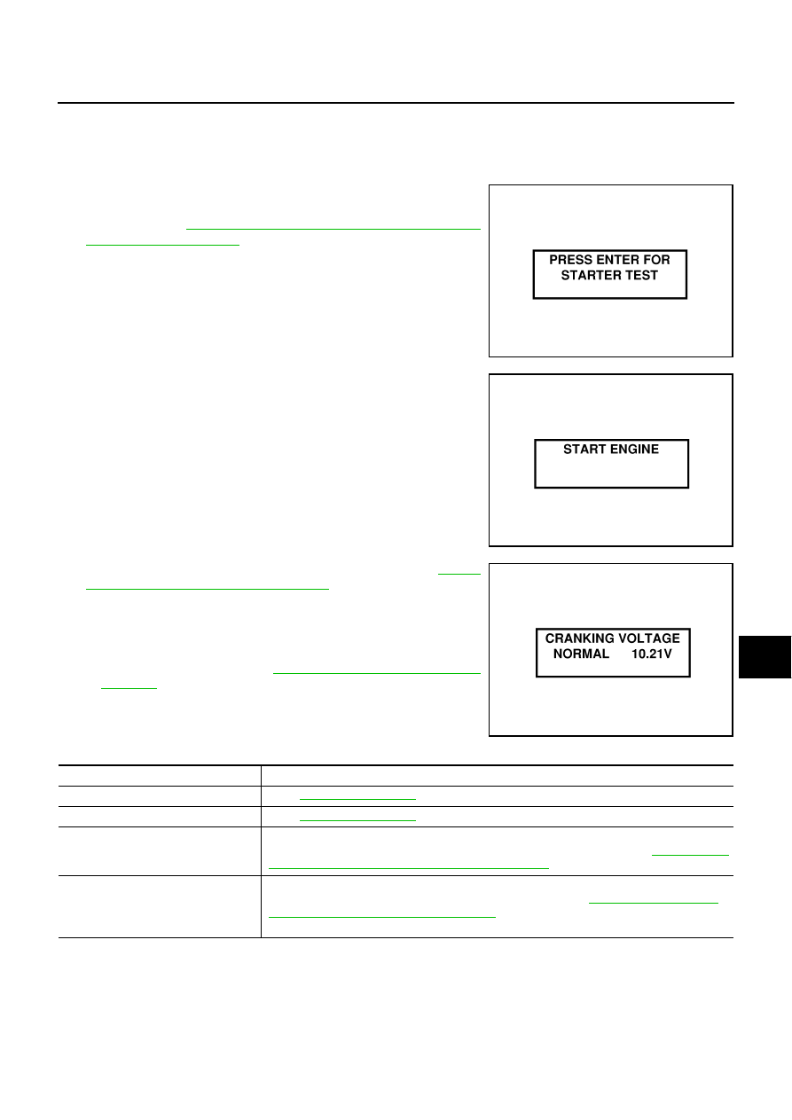
Press “ENTER” to begin the starting system test.

4.

Start the engine.

5.

Diagnosis result is displayed on the tester. Refer to 

SC-11,

"DIAGNOSTIC RESULT ITEM CHART"

 .

NOTE:

If the starter performs normally but the engine does not start,
perform engine diagnosis.

For intermittent “NO CRANK” or “NO STARTER OPERA-
TION” incidents, refer to 

SC-14, "DIAGNOSTIC PROCE-

DURE 2"

 .

DIAGNOSTIC RESULT ITEM CHART

SEL408X

SEL409X

SEL410X

Diagnostic item

Service procedure

CRANKING VOLTAGE NORMAL

Go to 

SC-12, "WORK FLOW"

 .

CRANKING VOLTAGE LOW

Go to 

SC-12, "WORK FLOW"

 .

CHARGE BATTERY

Perform the slow battery charging procedure. (Initial rate of charge is 10A for 12 hours.) Per-
form battery test again with Battery/Starting/Charging system tester. Refer to 

SC-6, "Trouble 

Diagnosis with Battery/Starting/Charging System Tester"

 .

REPLACE BATTERY

Before replacing battery, clean the battery cable clamps and battery posts. Perform battery 
test again with Battery/Starting/Charging system tester. Refer to 

SC-6, "Trouble Diagnosis 

with Battery/Starting/Charging System Tester"

 . If second test result is “REPLACE BAT-

TERY”, then do so. Perform battery test again to confirm repair.

STARTING SYSTEM

SC-13

C

D

E

F

G

H

I

J

L

M

A

B

SC

Revision: 2004 November

2004 Murano

DIAGNOSTIC PROCEDURE 1
Check “B” Terminal Circuit

1. 

CHECK POWER SUPPLY FOR STARTER MOTOR “B” TERMINAL

1.

Remove the fuel pump fuse.

2.

Crank or start the engine (where possible) until the fuel pressure is released.

3.

Turn the ignition switch OFF.

4.

Make sure the starter motor B terminal F38 terminal 2 (B/R) connection is clean and tight.

5.

Check voltage between starter motor B terminal F38 terminal 2
(B/R) and ground using a digital circuit tester.

OK or NG

OK

>> GO TO 2.

NG

>> Check harness between the battery and the starter

motor for open circuit.

2. 

CHECK BATTERY HARNESS CONNECTION (VOLTAGE DROP TEST)

Check voltage between starter motor B terminal F38 terminal 2 (B/R)
and battery positive terminal using a digital circuit tester.

OK or NG

OK

>> GO TO 3.

NG

>> Check harness between the battery and the starter

motor for poor continuity.

3. 

CHECK STARTER MOTOR GROUND CIRCUIT (VOLTAGE DROP TEST)

Check voltage between starter motor case and battery negative ter-
minal using a digital circuit tester.

OK or NG

OK

>> Starter motor “B” terminal circuit is OK. Further inspec-

tion necessary. Refer to 

SC-12, "WORK FLOW"

 .

NG

>> Check the starter motor case and ground for poor conti-

nuity.

Battery voltage should exist.

PKIA2369E

When the ignition switch is in START position, 
Voltage: Less than 0.5V

PKIA2370E

When the ignition switch is in START position, 
Voltage: Less than 0.2V

PKIA2786E

SC-14

STARTING SYSTEM

Revision: 2004 November

2004 Murano

DIAGNOSTIC PROCEDURE 2
Check “S” Connector Circuit

1. 

CHECK POWER SUPPLY FOR STARTER MOTOR “S” CONNECTOR

1.

Remove the fuel pump fuse.

2.

Crank or start the engine (where possible) until the fuel pressure is released.

3.

Turn the ignition switch OFF.

4.

Disconnect starter motors connector.

5.

Check voltage between starter motor harness connector F5 ter-
minal 1 (B/W) and ground using a digital circuit tester.

OK or NG

OK

>> GO TO 2.

NG

>> Check the following.

40A fusible link (letter M , located in the fuse and fus-
ible link block)

Ignition switch

Starter relay [within the IPDM (intelligent power distribution module engine room)]

Harness for open or short

2. 

CHECK “S” CONNECTOR CONNECTION (VOLTAGE DROP TEST)

1.

Connect starter motors connector.

2.

Check voltage between starter motor harness connector F5 ter-
minal 1 (B/W) and battery positive terminal using a digital circuit
tester.

OK or NG

OK

>> Starter motor “S” connector circuit is OK. Further inspec-

tion necessary. Refer to 

SC-12, "WORK FLOW"

 .

NG

>> Check harness between the battery and the starter

motor “S” connector for poor continuity.

MINIMUM SPECIFICATION OF CRANKING VOLTAGE REFERENCING COOLANT TEMPERA-
TURE

When the ignition switch is in START position, 
Battery voltage should exist.

PKIA2422E

When the ignition switch is in START position, 
Voltage: Less than 1V

PKIA2423E

Engine coolant temperature

Voltage V

30

°

C to 

20

°

C (

22

°

F to 

4

°

F)

8.4

19

°

C to 

10

°

C (

2

°

F to 14

°

F)

8.9

9

°

C to 0

°

C (16

°

F to 32

°

F)

9.3

More than 1

°

C (More than 34

°

F)

9.7

STARTING SYSTEM

SC-15

C

D

E

F

G

H

I

J

L

M

A

B

SC

Revision: 2004 November

2004 Murano

Removal and Installation 

AKS004F2

REMOVAL 

1.

Remove battery. Refer to 

SC-8, "Removal and Installation"

 .

2.

Remove air intake duct. Refer to 

EM-14, "AIR CLEANER AND AIR DUCT"

  in “ENGINE MECHANICAL

(EM)” section.

3.

Remove battery bracket, using power tools.

4.

Remove fluid charging pipe. Refer to 

CVT-224, "Removal and

Installation"

  in “CVT” section.

5.

Disconnect S connector.

6.

Remove B terminal nut.

7.

Remove starter motor mounting bolts, using power tools.

8.

Remove starter motor to the direction of upper side the vehicle.

INSTALLATION

Install in the reverse order of removal.

CAUTION:

Be sure to tighten B terminal nut carefully.

1.

Starter motor

2.

B terminal harness

3.

B terminal nut

4.

S connector

PKIA2424E

PKIA2851E

PKIA2425E

SC-16

STARTING SYSTEM

Revision: 2004 November

2004 Murano

Disassembly and Assembly 

AKS004F3

Inspection After Disassembly 

AKS004F4

PINION/CLUTCH CHECK

1.

Inspect pinion teeth.

Replace pinion if teeth are worn or damaged. (Also check condition of ring gear teeth.)

2.

Inspect reduction gear teeth.

Replace reduction gear if teeth are worn or damaged. (Also check condition of armature shaft gear
teeth.)

3.

Check to see if pinion locks in one direction and rotates smoothly in the opposite direction.

If it locks or rotates in both directions, or unusual resistance is evident, replace.

1.

Stopper ring

2.

Pinion stopper

3.

Pinion assembly

4.

Pinion spring

5.

Front bracket assembly

6.

Shift lever

7.

Plate

8.

Packing

9.

Plate

10. Magnetic switch assembly

11. Clutch gear assembly

12. Internal gear assembly

13. Gear shaft assembly

14. Gear assembly

15. Ball

16. Packing

17. Yoke assembly

18. Armature assembly

19. Brush assembly

20. Metal

21. Rear cover

Through-bolt

: 5.6 - 10.4 N·m (0.57 - 1.1 kg-m, 50 - 92 in-lb)

PKIA2426E

CHARGING SYSTEM

SC-17

C

D

E

F

G

H

I

J

L

M

A

B

SC

Revision: 2004 November

2004 Murano

CHARGING SYSTEM

PFP:23100

System Description

AKS004F5

The alternator provides DC voltage to operate the vehicle's electrical system and to keep the battery charged.
The voltage output is controlled by the IC regulator.
Power is supplied at all times:

through 10A fuse (No. 33, located in the fuse and fusible link block)

to alternator terminal 4 (S).

Terminal B supplies power to charge the battery and operate the vehicle's electrical system. Output voltage is
controlled by the IC regulator at terminal 4 (S) detecting the input voltage.
The alternator is grounded to the engine block.
With the ignition switch in the ON or START position, power is supplied:

through 10A fuse [No. 14, located in the fuse block (J/B)]

to combination meter terminal 20 for the charge warning lamp.

Ground is supplied:

to combination meter terminal 4

through alternator terminal 3 (L)

to alternator terminal E

through body ground E29.

With power and ground supplied, the charge warning lamp will illuminate. When the alternator is providing suf-
ficient voltage with the engine running, the ground is opened and the charge warning lamp will go off.
If the charge warning lamp illuminates with the engine running, a malfunction is indicated.

SC-18

CHARGING SYSTEM

Revision: 2004 November

2004 Murano

Wiring Diagram — CHARGE —

AKS004F6

TKWA0735E

CHARGING SYSTEM

SC-19

C

D

E

F

G

H

I

J

L

M

A

B

SC

Revision: 2004 November

2004 Murano

Trouble Diagnosis with Battery/Starting/Charging System Tester

AKS004F7

NOTE:
To ensure a complete and thorough diagnosis, the battery, starter and alternator test segments must be done
as a set from start to finish.

1.

Turn off all loads on the vehicle electrical system.

2.

Perform battery and starting system test with Battery/Starting/
Charging system tester.

3.

Press “ENTER” to begin the charging system test.

4.

Start engine.

5.

Press “ENTER” until “LOADS OFF REV ENGINE 5 SEC” is dis-
played.

6.

Raise and hold the engine speed at 1,500 to 2,000 rpm for about
5 seconds, then return the engine to idle.
Once the increase in engine rpm is detected, press “ENTER” to
continue.

NOTE:

If after 30 seconds an increase in engine idle speed is not
detected, “RPM NOT DETECTED” will display.

Some engines may have a higher idle initially after starting,
particularly when the engine is cold. The tester may detect
this without any other action being taken. If this occurs, con-
tinue on with the testing process. The final results will not be affected.

7.

The tester now checks the engine at idle and performs the
DIODE/RIPPLE check.

8.

When complete, the tester will prompt you to turn on the follow-
ing electrical loads.

Heater fan set to highest speed. Do not run the A/C or wind-
shield defroster.

Headlamp high beam

Rear window defogger

NOTE:
Do not run the windshield wipers or any other cyclical loads.

9.

Press “ENTER” to continue.

SEL417X

SEL418X

SEL419X

SEL420X

SC-20

CHARGING SYSTEM

Revision: 2004 November

2004 Murano

10. Raise and hold the engine speed at 1,500 to 2,000 rpm for about

5 seconds, then return the engine to idle. Once the increase in
engine rpm is detected, press “ENTER” to continue.

NOTE:
If after 30 seconds an increase in engine idle speed is not
detected, “RPM NOT DETECTED” will be displayed. Press
“ENTER” to restart the test.

11. Diagnostic result is displayed on the tester. Refer to 

SC-20,

"DIAGNOSTIC RESULT ITEM CHART"

 .

12. Press “ENTER” then test output code is displayed. Record the

test output code on the repair order.

13. Toggle back to the “DIAGNOSTIC SCREEN” for test results.

DIAGNOSTIC RESULT ITEM CHART

SEL421X

SEL422X

SEL577X

Diagnostic item

Service procedure

CHARGING SYSTEM NORMAL

Charging system is normal and will also show DIODE RIPPLE test result.

NO CHARGING VOLTAGE

Go to 

SC-21, "WORK FLOW"

 .

LOW CHARGING VOLTAGE

Go to 

SC-21, "WORK FLOW"

 .

HIGH CHARGING VOLTAGE

Go to 

SC-21, "WORK FLOW"

 .

DIODE RIPPLE NORMAL

Diode ripple is OK and will also show CHARGING VOLTAGE test result.

EXCESS RIPPLE DETECTED

Replace the alternator. Perform “DIODE RIPPLE” test again using Battery/Starting/Charging 
system tester to confirm repair.

DIODE RIPPLE NOT DETECTED

Go to 

SC-21, "WORK FLOW"

 .

CHARGING SYSTEM

SC-21

C

D

E

F

G

H

I

J

L

M

A

B

SC

Revision: 2004 November

2004 Murano

WORK FLOW

PKIA2226E

SC-22

CHARGING SYSTEM

Revision: 2004 November

2004 Murano

DIAGNOSTIC PROCEDURE 1
Check “L” Terminal Circuit

1. 

CHECK “L” TERMINAL CONNECTION

Check to see if “L” terminal is clean and tight.

OK or NG

OK

>> GO TO 2.

NG

>> Repair “L” terminal connection. Confirm repair by performing complete Battery/Starting/Charging

system test.

2. 

CHECK “L” TERMINAL CIRCUIT

1.

Disconnect alternator connector.

2.

Apply ground to alternator harness connector F27 terminal 3
(BR) with the ignition switch in the ON position.

OK or NG

OK

>> Go to 

SC-21, "WORK FLOW"

 .

NG

>> Check the following.

10A fuse [No. 14, located in the fuse block (J/B)]

CHARGE lamp

Harness for open or short between combination
meter and fuse

Harness for open or short between combination meter and alternator

CHARGE lamp should light up.

PKIA2427E

CHARGING SYSTEM

SC-23

C

D

E

F

G

H

I

J

L

M

A

B

SC

Revision: 2004 November

2004 Murano

DIAGNOSTIC PROCEDURE 2
Check “B” Terminal Circuit

1. 

CHECK “B” TERMINAL CONNECTION

Check to see if “B” terminal is clean and tight.

OK or NG

OK

>> GO TO 2. Confirm repair by performing complete Battery/Starting/Charging system test.

NG

>> Repair “B” terminal connection.

2. 

CHECK ALTERNATOR “B” TERMINAL CIRCUIT

Check voltage between alternator B terminal F26 terminal 1 (B/R)
and ground using a digital circuit tester.

OK or NG

OK

>> GO TO 3.

NG

>> Check harness for open or short between alternator and

battery.

3. 

CHECK “B” TERMINAL CONNECTION (VOLTAGE DROP TEST)

1.

Start the engine.

2.

When the engine running at idle and warm, check voltage
between alternator B terminal F26 terminal 1 (B/R) and battery
positive terminal using a digital circuit tester.

OK or NG

OK

>> Replace the alternator. Confirm repair by performing

complete Battery/Starting/Charging system test.

NG

>> Check harness between the battery and the alternator

for poor continuity.

Battery voltage should exist.

PKIA2367E

Voltage: Less than 0.2V

PKIA2366E

SC-24

CHARGING SYSTEM

Revision: 2004 November

2004 Murano

DIAGNOSTIC PROCEDURE 3
Check “L” Terminal Circuit

1. 

CHECK “L” TERMINAL CONNECTION

Check to see if “L” terminal is clean and tight.

OK or NG

OK

>> GO TO 2.

NG

>> Repair “L” terminal connection. Confirm repair by performing complete Battery/Starting/Charging

system test.

2. 

CHECK “L” TERMINAL CIRCUIT

1.

Disconnect alternator connector.

2.

Apply ground to alternator harness connector F27 terminal 3
(BR) with the ignition switch in the ON position.

OK or NG

OK

>> Replace the alternator. Confirm repair by performing

complete Battery/Starting/Charging system test.

NG

>> Check the following.

10A fuse [No. 14, located in the fuse block (J/B)]

CHARGE lamp

Harness for open or short between combination
meter and fuse

Harness for open or short between combination meter and alternator

CHARGE lamp should light up.

PKIA2427E

CHARGING SYSTEM

SC-25

C

D

E

F

G

H

I

J

L

M

A

B

SC

Revision: 2004 November

2004 Murano

DIAGNOSTIC PROCEDURE 4
Check “B” Terminal Circuit

1. 

CHECK “B” TERMINAL CONNECTION

Check to see if “B” terminal is clean and tight.

OK or NG

OK

>> GO TO 2. Confirm repair by performing complete Battery/Starting/Charging system test.

NG

>> Repair “B” terminal connection.

2. 

CHECK ALTERNATOR “B” TERMINAL CIRCUIT

Check voltage between alternator B terminal F26 terminal 1 (B/R)
and ground using a digital circuit tester.

OK or NG

OK

>> GO TO 3.

NG

>> Check harness for open or short between alternator and

battery.

3. 

CHECK “B” TERMINAL CONNECTION (VOLTAGE DROP TEST)

1.

Start the engine.

2.

When the engine running at idle and warm, check voltage
between alternator B terminal F26 terminal 1 (B/R) and battery
positive terminal using a digital circuit tester.

OK or NG

OK

>> GO TO 4.

NG

>> Check harness between the battery and the alternator

for poor continuity.

4. 

CHECK ALTERNATOR DRIVE BELT TENSION

1.

Turn ignition switch OFF.

2.

Check alternator drive belt tension. Refer to 

EM-11, "Checking Drive Belts"

  in “ENGINE MECHANICAL

(EM)” section.

YES or NO

YES

>> Replace the alternator. Confirm repair by performing complete Battery/Starting/Charging system

test.

NO

>> Readjust belt tension. Refer to 

EM-11, "Tension Adjustment"

  in “ENGINE MECHANICAL (EM)”

section.

Battery voltage should exist.

PKIA2367E

Voltage: Less than 0.2V

PKIA2366E

Does drive belt tension normal?

SC-26

CHARGING SYSTEM

Revision: 2004 November

2004 Murano

DIAGNOSTIC PROCEDURE 5
Check “S” Terminal Circuit

1. 

CHECK “S” TERMINAL CONNECTION

Check to see if “S” terminal is clean and tight.

OK or NG

OK

>> GO TO 2.

NG

>> Repair “S” terminal connection. Confirm repair by performing complete Battery/Starting/Charging

system test.

2. 

CHECK ALTERNATOR “S” TERMINAL CIRCUIT

Check voltage between alternator harness connector F27 terminal 4
(Y/B) and ground using a digital circuit tester.

OK or NG

OK

>> GO TO 3.

NG

>> Check the following.

10A fuse (No. 33, located in the fuse and fusible link
box)

Harness for open or short between alternator and
fuse

3. 

CHECK “S” TERMINAL CONNECTION (VOLTAGE DROP TEST)

1.

Start the engine.

2.

When the engine running at idle and warm, check voltage
between alternator connector F27 terminal 4 (Y/B) and battery
positive terminal using a digital circuit tester.

OK or NG

OK

>> Replace the alternator. Confirm repair by performing

complete Battery/Starting/Charging system test.

NG

>> Check harness between the battery and the alternator

for poor continuity.

MALFUNCTION INDICATOR

The IC regulator warning function activates to illuminate “CHARGE” warning lamp, if any of the following
symptoms occur while alternator is operating:

Excessive voltage is produced.

No voltage is produced.

Battery voltage should exist.

PKIA2428E

Voltage: Less than 0.2V

PKIA2429E


Content      ..     202      203      204      205     ..