Nissan Murano Z50 (2004 year). Manual - part 190


  Index      Manuals     Nissan Murano Z50 (2004 year) - Service and Repair Manual


Search            copyright infringement  


Content      ..     188      189      190      191     ..


Nissan Murano Z50 (2004 year). Manual - part 190


IPDM E/R (INTELLIGENT POWER DISTRIBUTION MODULE ENGINE ROOM)

PG-21

C

D

E

F

G

H

I

J

L

M

A

B

PG

Revision: 2004 November

2004 Murano

DATA MONITOR
Operation Procedure

1.

Touch “DATA MONITOR” on “SELECT MONITOR ITEM ” screen.

2.

Touch “ALL SIGNALS”, “MAIN SIGNALS” or “SELECTION FROM MENU” on the “DATA MONITOR”
screen.

3.

Touch “START”.

4.

Touch the required monitoring item on “SELECTION FROM MENU”. In “ALL SIGNALS”, all items are
monitored. In “MAIN SIGNALS”, predetermined items are monitored.

5.

Touch “RECORD” while monitoring to record the status of the item being monitored. To stop recording,
touch “STOP”.

All Signals, Main Signals, Selection From Menu

NOTE:

Perform monitoring of IPDM E/R data with the ignition switch ON. When the ignition switch is at ACC, the
display may not be correct.

The head lamp washer request items are displayed, but they cannot be monitored.

The Day time light request items are displayed, but they cannot be monitored.

ALL SIGNALS

All items will be monitored.

MAIN SIGNALS

Monitor the predetermined item.

SELECTION FROM MENU

Select any item for monitoring.
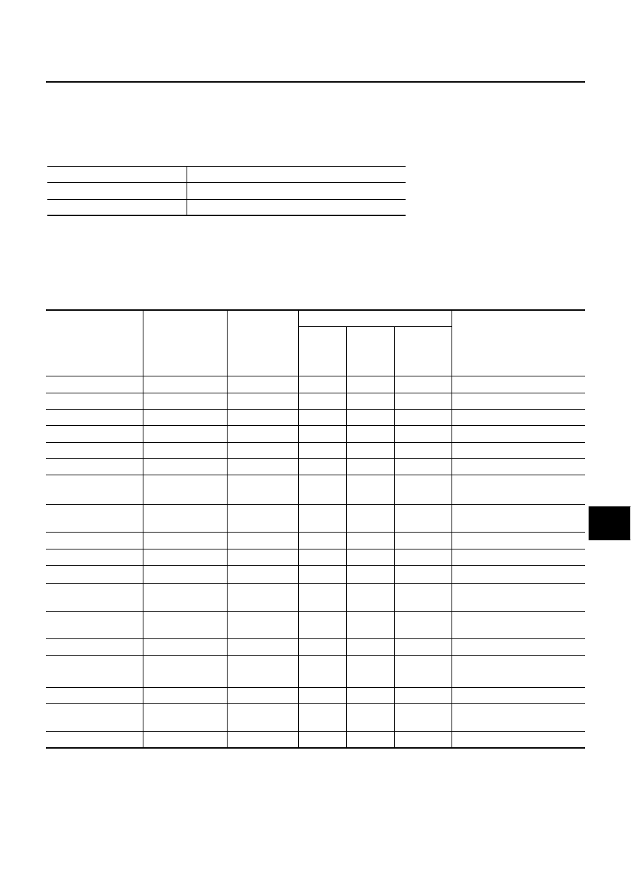
Item name

CONSULT-II 

screen display

Display or unit

Monitor item selection

Description

ALL

SIGNALS

MAIN 

SIGNALS

SELEC-

TION 

FROM 
MENU

Motor fan request

MOTOR FAN REQ

1/2/3/4

×

×

×

Signal status input from ECM

Compressor request

AC COMP REQ

ON/OFF

×

×

×

Signal status input from ECM

Tail & clear request

TAIL&CLR REQ

ON/OFF

×

×

×

Signal status input from BCM

H/L LO request

HL LO REQ

ON/OFF

×

×

×

Signal status input from BCM

H/L HI request

HL HI REQ

ON/OFF

×

×

×

Signal status input from BCM

Front fog request 

FR FOG REQ

ON/OFF

×

×

×

Signal status input from BCM

Head lamp washer 

request

NOTE

HL WASHER REQ

ON/OFF

×

×

Signal status input from BCM

Front wiper request

FR WIP REQ

STOP/1LOW/

LOW/HI

×

×

×

Signal status input from BCM

Wiper auto stop

WIP AUTO STOP

ACT P/STOP P

×

×

×

Output status of IPDM E/R

Wiper protection

WIP PROT

OFF/Block

×

×

×

Control status of IPDM E/R

Starter request

ST RLY REQ

ON/OFF

×

×

Status of input signal 

NOTE

Ignition relay status

IGN RLY

ON/OFF

×

×

×

Ignition relay status monitored 
with IPDM E/R

Rear window defog-
ger request

RR DEF REQ

ON/OFF

×

×

×

Signal status input from BCM

Oil pressure switch 

OIL P SW

OPEN/CLOSE

×

×

Signal status input in IPDM E/R

Day time light request


NOTE

DTRL REQ

ON/OFF

×

×

Signal status input from BCM

Hood switch

HOOD SW

ON/OFF

×

×

Signal status input in IPDM E/R

Theft warning horn 
request

THFT HRN REQ

ON/OFF

×

×

Signal status input from BCM

Horn chirp

HORN CHIRP

ON/OFF

×

×

Output status of IPDM E/R

PG-22

IPDM E/R (INTELLIGENT POWER DISTRIBUTION MODULE ENGINE ROOM)

Revision: 2004 November

2004 Murano

ACTIVE TEST
Operation Procedure

1.

Touch “ACTIVE TEST” on “SELECT DIAG MODE” screen.

2.

Touch item to be tested, and check operation.

3.

Touch “START”.

4.

Touch “STOP” while testing to stop the operation.

NOTE:
The headlamp washer items are displayed, but they cannot be tested.

Test item

CONSULT-II screen display

Description

Tail lamp output

TAIL LAMP

With a certain ON-OFF operation, the tail lamp relay can be oper-
ated.

Rear window defogger output

REAR DEFOGGER

With a certain ON-OFF operation, the rear window defogger relay 
can be operated.

Front wiper (HI, LO) output

FRONT WIPER

With a certain operation (OFF, HI ON, LO ON), the front wiper relay 
(Lo, Hi) can be operated.

Cooling fan output

MOTOR FAN

With a certain operation (1,2,3,4), the cooling fan can be operated.

Headlamp washer

HEAD LAMP WASHER

Lamp (HI, LO, FOG

NOTE

 ) out-

put

LAMPS

With a certain operation (OFF, HI ON, LO ON, FOG ON

NOTE

 ), the 

lamp relay (Lo, Hi, Fog

NOTE

 ) can be operated.

Horn output

HORN

Push “ON” button, horn relay operates 20ms.

IPDM E/R (INTELLIGENT POWER DISTRIBUTION MODULE ENGINE ROOM)

PG-23

C

D

E

F

G

H

I

J

L

M

A

B

PG

Revision: 2004 November

2004 Murano

Auto Active Test

AKS00A4E

DESCRIPTION

In auto active test mode, operation inspection can be performed when IPDM E/R sends a drive signal to
the following systems:

Rear window defogger

Front wipers

Tail and parking lamps

Front fog lamps

Headlamps (Hi, Lo)

A/C compressor (magnetic clutch)

Cooling fan

OPERATION PROCEDURE

1.

Close hood front door RH and lift wiper arms away from windshield (to prevent glass damage by wiper
operation).

NOTE:
When auto active test is performed with hood opened, sprinkle water on windshield beforehand.

2.

Turn ignition switch OFF.

3.

Turn ignition switch ON and, within 20 seconds, open and close 10 times of front door LH. Then turn igni-
tion switch OFF.

4.

Turn ignition switch ON within 10 seconds after ignition switch OFF. 

5.

When auto active test mode is actuated, horn chirps once.

6.

After a series of operations is repeated three times, auto active test is completed.

NOTE:
When auto active test mode has to be cancelled halfway, turn ignition switch OFF.

CAUTION:

Be sure to inspec

BL-37, "Check Door Switch"

  when the auto active test cannot be performed.

INSPECTION IN AUTO ACTIVE TEST MODE

When auto active test mode is actuated, the following eight steps are repeated three times.

NOTE:
Turns ON-OFF the solenoid to switch Hi/Lo. In this case, the bulb does not illuminate.

SKIA4046E

PG-24

IPDM E/R (INTELLIGENT POWER DISTRIBUTION MODULE ENGINE ROOM)

Revision: 2004 November

2004 Murano

Concept of Auto Active Test

IPDM E/R actuates auto active test mode when it receives door switch signal from BCM via CAN commu-
nication line. Therefore, when auto active test mode is activated successfully, CAN communication
between IPDM E/R and BCM is normal.

If any of systems controlled by IPDM E/R cannot be operated, possible cause can be easily diagnosed
using auto active test.

Diagnosis chart in auto active test mode

Symptom

Inspection contents

Possible cause

Any of front wipers, tail 
and parking lamps, front 
fog lamps, and head 
lamps (Hi, Lo) do not 
operate.

Perform auto active 
test. Does system in 
question operate?

YES

BCM signal input system

NO

Lamp/wiper motor malfunction

Lamp/wiper motor ground circuit malfunction

Harness/connector malfunction between IPDM E/R and system in 
question

IPDM E/R (integrated relay) malfunction

Rear window defogger 
does not operate.

Perform auto active 
test. Does rear win-
dow defogger oper-
ate?

YES

BCM signal input circuit

NO

Rear window defogger relay circuit

Open circuit of rear window defogger

IPDM E/R malfunction

A/C compressor does 
not operate.

Perform auto active 
test. Does magnetic 
clutch operate?

YES

BCM signal input circuit

CAN communication signal between BCM and ECM.

CAN communication signal between ECM and IPDM E/R

NO

Magnetic clutch malfunction

Harness/connector malfunction between IPDM E/R and magnetic 
clutch

IPDM E/R (integrated relay) malfunction

Cooling fan does not 
operate.

Perform auto active 
test. Does cooling fan 
operate?

YES

ECM signal input circuit

CAN communication signal between ECM and IPDM E/R

NO

Cooling fan motor malfunction

Harness/connector malfunction between IPDM E/R and cooling fan 
motor

IPDM E/R (integrated relay) malfunction

Oil pressure warning 
lamp does not operate.

Perform auto active 
test. Does oil pres-
sure warning lamp 
blink?

YES

Harness/connector malfunction between IPDM E/R and oil pressure 
switch

Oil pressure switch malfunction

IPDM E/R malfunction

NO

CAN communication signal between BCM and Unified Meter and A/C 
Amp

Combination meter

IPDM E/R (INTELLIGENT POWER DISTRIBUTION MODULE ENGINE ROOM)

PG-25

C

D

E

F

G

H

I

J

L

M

A

B

PG

Revision: 2004 November

2004 Murano

Schematic

AKS00A4F

TKWA1754E

PG-26

IPDM E/R (INTELLIGENT POWER DISTRIBUTION MODULE ENGINE ROOM)

Revision: 2004 November

2004 Murano

IPDM E/R Terminal Arrangement

AKS00A4G

CKIA0346E

IPDM E/R (INTELLIGENT POWER DISTRIBUTION MODULE ENGINE ROOM)

PG-27

C

D

E

F

G

H

I

J

L

M

A

B

PG

Revision: 2004 November

2004 Murano

IPDM E/R Power/Ground Circuit Inspection

AKS00A4H

1. 

CHECK FUSE AND FUSIBLE LINK

Make sure the following fusible links or IPDM E/R fuses are not blown.

OK or NG

OK

>> GO TO 2.

NG

>> Replace fuse or fusible link.

2. 

CHECK POWER SUPPLY CIRCUIT

1.

Turn ignition switch OFF.

2.

Disconnect IPDM E/R harness connector E3.

3.

Check voltage between IPDM E/R harness connector E3 termi-
nals 1 (R), 2 (W/L) and ground.

OK or NG

OK

>> GO TO 3.

NG

>> Replace IPDM E/R power supply circuit harness.

3. 

CHECK GROUND CIRCUIT

1.

Disconnect IPDM E/R harness connectors E8 and E9.

2.

Check continuity between IPDM E/R harness connectors E8 ter-
minal 38 (B), E9 terminal 50 (B), 60 (B) and ground.

OK or NG

OK

>> INSPECTION END

NG

>> Replace ground circuit harness of IPDM E/R.

Terminal No.

Signal name

Fuse, fusible link No.

1, 2, 16

Battery power

F/L–C, F/L–E, F/L–L, Fuse No. 71, 78

Battery voltage should exist

SKIA6183E

Continuity should exist

SKIA6184E

PG-28

IPDM E/R (INTELLIGENT POWER DISTRIBUTION MODULE ENGINE ROOM)

Revision: 2004 November

2004 Murano

Inspection With CONSULT-II (Self-Diagnosis)

AKS00A4I

CAUTION:

If CONSULT-II is used with no connection of CONSULT-II CONVERTER, malfunctions might be
detected in self-diagnosis depending on control unit which carry out CAN communication.

1. 

CHECK SELF DIAGNOSTIC RESULT

1.

Connect CONSULT-II and select “IPDM E/R” on the Diagnosis System Selection screen.

2.

Select “SELF-DIAG RESULTS” on the “SELECT DIAG MODE” screen.

3.

Check display content in self diagnostic results.

NOTE:
The Details for Display of the Period Are as Follows:

CRNT: Error currently detected with IPDM E/R.

PAST: Error detected in the past and memorized with IPDM E/R.

Contents displayed

NO DTC IS DETECTED.FURTHER TESTING MAY BE REQUIRED.>>INSPECTION END
CAN COMM CIRC>>After print-out of the monitor items, refer to 

LAN-6, "Precautions When Using CON-

SULT-II"

 .

CONSULT-II display

CONSULT-II 
display code

TIME

Details of diagnosis result

CRNT

PAST

NO DTC IS DETECTED.

FURTHER TESTING MAY BE REQUIRED.

-

-

-

No malfunction

CAN COMM CIRC

U1000

×

×

Any of or several items below have errors.

TRANSMIT DIAG

ECM

BCM/SEC

IPDM E/R (INTELLIGENT POWER DISTRIBUTION MODULE ENGINE ROOM)

PG-29

C

D

E

F

G

H

I

J

L

M

A

B

PG

Revision: 2004 November

2004 Murano

Removal and Installation of IPDM E/R

AKS00AAF

REMOVAL

1.

Remove IPDM E/R cover A and IPDM E/R cover. 

2.

While spreading pawls on both side of IPDM E/R cover B,
remove  IPDM E/R from IPDM E/R cover B.

3.

Remove harness connector from IPDM E/R.

INSTALLATION

Install in the revers order of removal.

SKIA4048E

PG-30

GROUND

Revision: 2004 November

2004 Murano

GROUND 

PFP:00011

Ground Distribution 

AKS007HJ

MAIN HARNESS

CKIA0347E

GROUND

PG-31

C

D

E

F

G

H

I

J

L

M

A

B

PG

Revision: 2004 November

2004 Murano

CKIA0348E

PG-32

GROUND

Revision: 2004 November

2004 Murano

CKIA0349E

GROUND

PG-33

C

D

E

F

G

H

I

J

L

M

A

B

PG

Revision: 2004 November

2004 Murano

ENGINE ROOM HARNESS 

CKIA0350E

PG-34

GROUND

Revision: 2004 November

2004 Murano

CKIA0280E

GROUND

PG-35

C

D

E

F

G

H

I

J

L

M

A

B

PG

Revision: 2004 November

2004 Murano

ENGINE CONTROL HARNESS

CKIA0281E

PG-36

GROUND

Revision: 2004 November

2004 Murano

BODY HARNESS

CKIA0352E


Content      ..     188      189      190      191     ..