Nissan Murano Z50 (2004 year). Manual - part 160
CAN SYSTEM (TYPE 11)
LAN-377
[CAN]
C
D
E
F
G
H
I
J
L
M
A
B
LAN
Revision: 2004 November
2004 Murano
2.
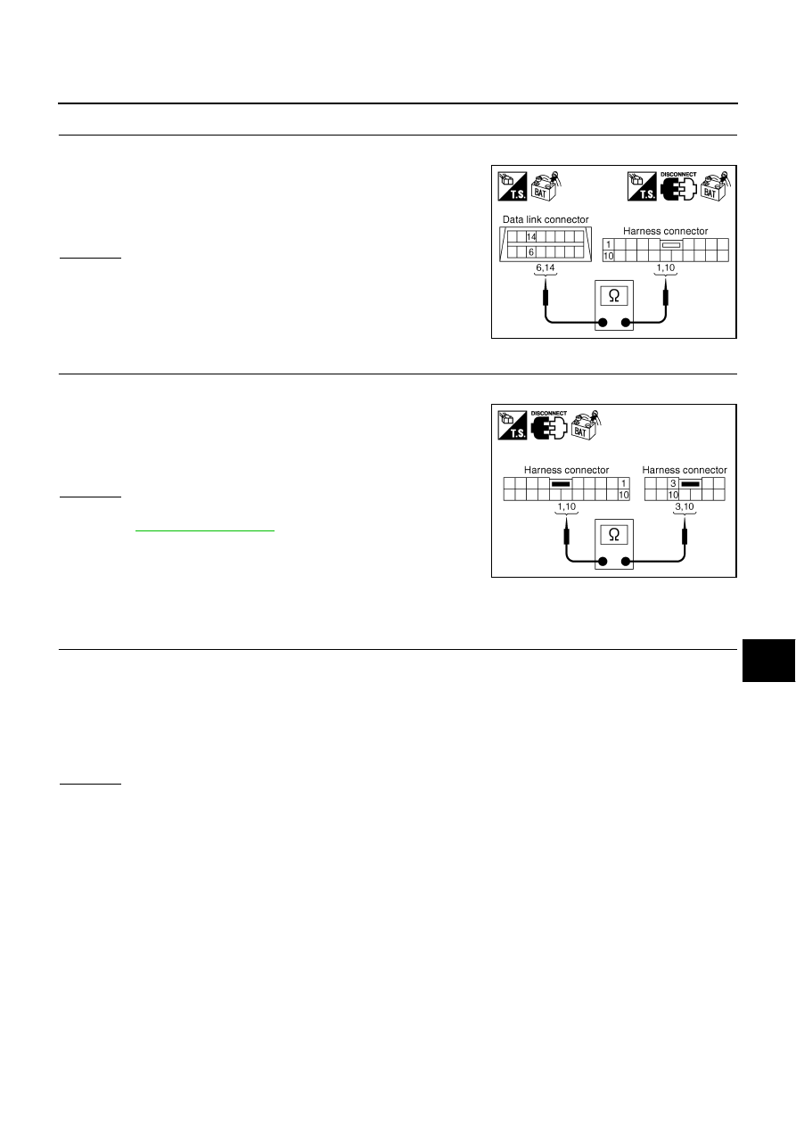
CHECK HARNESS FOR OPEN CIRCUIT
1.
Disconnect harness connector M9.
2.
Check continuity between data link connector M24 terminals 6
(L), 14 (Y) and harness connector M9 terminals 1 (L), 10 (Y).
OK or NG
OK
>> GO TO 3.
NG
>> Repair harness.
3.
CHECK HARNESS FOR OPEN CIRCUIT
1.
Disconnect harness connector B4.
2.
Check continuity between harness connector B2 terminals 1 (L),
10 (Y) and harness connector B4 terminals 3 (L), 10 (Y).
OK or NG
OK
>> Connect all the connectors and diagnose again. Refer to
.
NG
>> Repair harness.
Circuit Check Between Driver Seat Control Unit and ABS Actuator and Electric
Unit (Control Unit)
AKS00AI2
1.
CHECK CONNECTOR
1.
Turn ignition switch OFF.
2.
Disconnect the negative battery terminal.
3.
Check following terminals and connectors for damage, bend and loose connection (connector side and
harness side).
–
Harness connector B4
–
Harness connector E105
OK or NG
OK
>> GO TO 2.
NG
>> Repair terminal or connector.
6 (L) - 1 (L)
: Continuity should exist.
14 (Y) - 10 (Y)
: Continuity should exist.
SKIA5015E
1 (L) - 3 (L)
: Continuity should exist.
10 (Y) - 10 (Y)
: Continuity should exist.
SKIA5016E