Nissan Murano Z50 (2004 year). Manual - part 149
CAN SYSTEM (TYPE 6)
LAN-201
[CAN]
C
D
E
F
G
H
I
J
L
M
A
B
LAN
Revision: 2004 November
2004 Murano
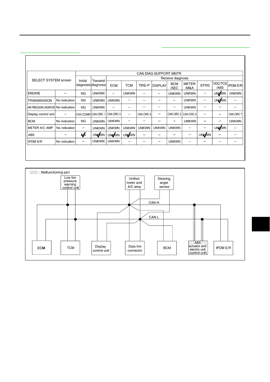
Case 11
Check ABS actuator and electric unit (control unit) circuit. Refer to
LAN-210, "ABS Actuator and Electric Unit
.
PKIA8434E
SKIA5263E