Nissan Murano Z50 (2004 year). Manual - part 134


  Index      Manuals     Nissan Murano Z50 (2004 year) - Service and Repair Manual


Search            copyright infringement  


Content      ..     132      133      134      135     ..


Nissan Murano Z50 (2004 year). Manual - part 134


GW-80

REAR WINDOW DEFOGGER

Revision: 2004 November

2004 Murano

6. 

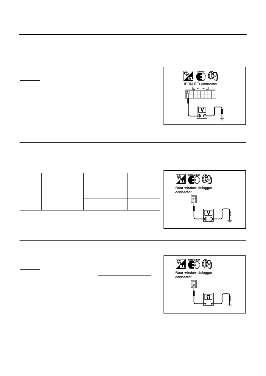
CHECK REAR WINDOW DEFOGGER RELAY OUTPUT SIGNAL

1.

Connect IPDM E/R and rear window defogger relay.

2.

Turn ignition switch ON.

3.

Check voltage between IPDM E/R connector E9 terminal 52 and ground.

OK or NG

OK

>> Replace IPDM E/R.

NG

>> Check the condition of the harness and the connector.

Rear Window Defogger Circuit Check

AIS002IN

1. 

CHECK POWER SUPPLY CIRCUIT 

1.

Turn ignition switch OFF.

2.

Disconnect rear window defogger connector.

3.

Turn ignition switch ON.

4.

Check voltage between rear window defogger connector  and ground.

OK or NG

OK

>> GO TO 2.

NG

>> GO TO 3.

2. 

CHECK GROUND CIRCUIT

1.

Turn ignition switch OFF.

2.

Check continuity between rear window defogger connector D107 terminal 2 and ground.

OK or NG

OK

>> Check filament.  Refer to 

GW-86, "Filament Check"

If filament is OK.
Check the condition of the harness and the connector.

If filament is NG.
Repair filament.

NG

>> Repair or replace harness between rear window defog-

ger and ground.

52 (G/R) – Ground

:Battery voltage

PIIA6210E

Connector

Terminal (Wire color)

Condition

Voltage (V)

(Approx.)

(+)

(–)

D97

1 (G)

Ground

Rear window defogger 
switch ON.

 Battery voltage

Rear window defogger  
switch OFF.

0

PIIA4234E

2 (B) 

 Ground

: Continuity should exist.

PIIA4235E

REAR WINDOW DEFOGGER

GW-81

C

D

E

F

G

H

J

K

L

M

A

B

GW

Revision: 2004 November

2004 Murano

3. 

CHECK HARNESS CONTINUITY

1.

Turn ignition switch OFF.

2.

Disconnect rear window defogger relay.

3.

Check continuity between rear window defogger relay connector B8 terminal 5 and rear window defogger
connector D97 terminal 1.

OK or NG

OK

>> Check the condition of the harness and the connector.

NG

>> Repair or replace harness rear window defogger relay

and rear window defogger. When there is malfunction
inside back door, replace the back door.

Door Mirror Defogger Power Supply Circuit Check

AIS002IO

1. 

CHECK FUSE 

Check 10A fuse [No. 8, located in the fuse block (J/B)]

NOTE:
Refer to 

GW-65, "Component Parts and Harness Connector Location"

 .

OK or NG

OK

>> GO TO 2.

NG

>> If fuse is blown, be sure to eliminate cause of malfunction before installing new fuse.  Refer to 

PG-

3, "POWER SUPPLY ROUTING CIRCUIT"

 .

2. 

CHECK POWER SUPPLY CIRCUIT 1

1.

Turn ignition switch ON.

2.

Check voltage between fuse block (J/B) connector and ground.

OK or NG

OK

>> GO TO 3.

NG

>> Repair or replace harness between rear window defogger relay and fuse block (J/B).

5 (G) – 1 (G)

: Continuity should exist.

PIIA4236E

Connector

Terminal (Wire color)

Condition

Voltage (V)

(Approx.)

(+)

(–)

E101

2C (G)

Ground

Rear window defogger 
switch ON

 Battery voltage

Rear window defogger 
switch OFF

0

PIIA2388E

GW-82

REAR WINDOW DEFOGGER

Revision: 2004 November

2004 Murano

3. 

CHECK POWER SUPPLY CIRCUIT 2

Check voltage between fuse block (J/B) connector and ground.

OK or NG

OK

>> GO TO 4. 

NG

>> Replace fuse block (J/B).

4. 

CHECK HARNESS CONTINUITY 

1.

Turn ignition switch OFF.

2.

Disconnect fuse block (J/B) and door mirror connector.

3.

Check continuity between fuse block (J/B) connector M5 terminal 5B and door mirror connector D2 (driver
side) or D32 (passenger side) terminal 1.

OK or NG

OK

>> GO TO 5.

NG

>> Repair or replace harness between fuse block (J/B) and

malfunction door mirror connector.

5. 

CHECK GROUND CIRCUIT

Check continuity between each door mirror connector D2 (driver side), D32 (passenger side) terminal 5 and
ground.

OK or NG

OK

>> GO TO 6.

NG

>> Repair or replace harness.

Connector

Terminal (Wire color)

Condition

Voltage (V)

(Approx.)

(+)

(–)

M5

5B (L)

Ground

Rear window defogger 
switch ON

 Battery voltage

Rear window defogger 
switch OFF

0

PIIA2386E

5B (B) – 1 (B)

: Continuity should exist.

PIIA4228E

5 (B) – Ground

: Continuity should exist.

PIIA4229E

REAR WINDOW DEFOGGER

GW-83

C

D

E

F

G

H

J

K

L

M

A

B

GW

Revision: 2004 November

2004 Murano

6. 

CHECK DOOR MIRROR DEFOGGER 

1.

Connector door mirror connector.

2.

Check continuity between each door mirror connector D2 (driver side), D32 (passenger side) terminals 1
and 5.

OK or NG

OK

>> Check the condition of the harness and the connector.

NG

>> Replace malfunctioning door mirror.

Driver Side Door Mirror Defogger Circuit Check

AIS002IP

1. 

CHECK POWER SUPPLY CIRCUIT 

1.

Turn ignition switch OFF.

2.

Disconnect door mirror (driver side) connector. 

3.

Turn ignition switch ON.

4.

Check voltage between door mirror (driver side) connector and ground.

OK or NG

OK

>> GO TO 2.

NG

>> Repair or replace harness between fuse block (J/B) and

door mirror (driver side).

2. 

CHECK GROUND CIRCUIT

1.

Turn ignition switch OFF.

2.

Check continuity between door mirror (driver side) connector D2
terminal 5 and ground.

OK or NG

OK

>> GO TO 3.

NG

>> Repair or replace harness between door mirror (driver

side) and ground.

1 (L/B) – 5 (L/B)

: Continuity should exist.

PIIA4230E

Connector

Terminal (Wire color)

Condition

Voltage (V)

(Approx.)

(+)

(–)

D2

1 (L/B)

Ground

Rear window defogger 
switch ON

 Battery voltage

Rear window defogger  
switch OFF

0

PIIA4231E

5 (B) – Ground

: Continuity should exist.

PIIA4229E

GW-84

REAR WINDOW DEFOGGER

Revision: 2004 November

2004 Murano

3. 

CHECK DOOR MIRROR DEFOGGER 

1.

Connector door mirror connector.

2.

Check continuity between each door mirror connector D2 (driver side) terminals 1 and 5.

OK or NG

OK

>> Check the condition of the harness and the connector.

NG

>> Replace door mirror (driver side).

Passenger Side Door Mirror Defogger Circuit Check 

AIS002IQ

1. 

CHECK POWER SUPPLY CIRCUIT

1.

Turn ignition switch OFF.

2.

Disconnect door mirror (passenger side) connector.

3.

Turn ignition switch ON.

4.

Check voltage between door mirror (passenger side) connector and ground.

OK or NG

OK

>> GO TO 2.

NG

>> Repair or replace harness between fuse block (J/B) and

door mirror (passenger side).

2. 

CHECK GROUND CIRCUIT

1.

Turn ignition switch OFF.

2.

Check continuity between door mirror (passenger side) connector D32 terminal 5 and ground.

OK or NG

OK

>> GO TO 3.

NG

>> Repair or replace harness between door mirror (passen-

ger side) and ground.

1 (L/B) – 5 (L/B)

: Continuity should exist.

PIIA4230E

Connector

Terminal (Wire color)

Condition

Voltage (V)

(Approx.)

(+)

(–)

D32

1 (L/B)

Ground

Rear window defogger 
switch ON

 Battery voltage

Rear window defogger 
switch OFF

0

PIIA4231E

5 (B) – Ground

: Continuity should exist.

PIIA4229E

REAR WINDOW DEFOGGER

GW-85

C

D

E

F

G

H

J

K

L

M

A

B

GW

Revision: 2004 November

2004 Murano

3. 

CHECK DOOR MIRROR DEFOGGER 

1.

Connector door mirror connector.

2.

Check continuity between each door mirror connector D32 (passenger side) terminals 1 and 5.

OK or NG

OK

>> Check the condition of the harness and the connector.

NG

>> Replace door mirror (passenger side).

Rear Window Defogger Signal Check

AIS002J2

1. 

CHECK REAR WINDOW DEFOGGER SWITCH LAMP

A/C and AV switch self-diagnosis is executed. Refer to 

AV-92, "A/C and AV Switch Self-Diagnosis Function"

OK or NG

OK

>> GO TO 2.

NG

>> Replace A/C and AV switch.

2. 

CHECK AV COMMUNICATION LINE

AV communication line check is executed.  Refer to 

AV-100, "A/C and AV Switch Does Not Operate"

OK or NG

OK

>> GO TO 3.

NG

>> Replace display control unit.

3. 

CHECK CAN COMMUNICATION LINE

CAN communication line check is executed. Refer to 

AV-101, "CAN Communication Line Check"

OK or NG

OK

>> Check the condition of the harness and the connector.

NG

>> In addition, it is necessary to check CAN communication line. Refer to 

AV-101, "CAN Communica-

tion Line Check"

1 (L/B) – 5 (L/B)

: Continuity should exist.

PIIA4230E

Does rear window defogger switch light?

Is rear window defogger displayed on the display?

GW-86

REAR WINDOW DEFOGGER

Revision: 2004 November

2004 Murano

Filament Check

AIS002IR

1.

When measuring voltage, wrap tin foil around the top of the neg-
ative probe. Then press the foil against the wire with your finger.

2.

Attach probe circuit tester (in Volt range) to middle portion of
each filament.

3.

If a filament is burned out, circuit tester registers 0 or battery
voltage.

4.

To locate burned out point, move probe to left and right along fil-
ament. Test needle will swing abruptly when probe passes the
point.

Filament Repair

AIS002IS

REPAIR EQUIPMENT

Conductive silver composition (Dupont No. 4817 or equivalent)

Ruler 30 cm (11.8 in) long

Drawing pen

Heat gun

Alcohol

Cloth

SEL122R

SEL263

SEL265

REAR WINDOW DEFOGGER

GW-87

C

D

E

F

G

H

J

K

L

M

A

B

GW

Revision: 2004 November

2004 Murano

REPAIRING PROCEDURE

1.

Wipe broken heat wire and its surrounding area clean with a
cloth dampened in alcohol.

2.

Apply a small amount of conductive silver composition to tip of
drawing pen.
Shake silver composition container before use.

3.

Place ruler on glass along broken line. Deposit conductive silver
composition on break with drawing pen. Slightly overlap existing
heat wire on both sides [preferably 5 mm (0.20 in)] of the break.

4.

After repair has been completed, check repaired wire for conti-
nuity. This check should be conducted 10 minutes after silver
composition is deposited.
Do not touch repaired area while test is being conducted.

5.

Apply a constant stream of hot air directly to the repaired area
for approximately 20 minutes with a heat gun. A minimum dis-
tance of 3 cm (1.2 in) should be kept between repaired area and
hot air outlet.
If a heat gun is not available, let the repaired area dry for 24
hours.

PIIA0215E

SEL012D

SEL013D

GW-88

DOOR MIRROR

Revision: 2004 November

2004 Murano

DOOR MIRROR

PFP:96301

Automatic Drive Positioner Interlocking Door Mirror 

AIS003I3

Automatic drive positioner interlocking door mirror. Refer to 

SE-12, "AUTOMATIC DRIVE POSITIONER"

 .

DOOR MIRROR

GW-89

C

D

E

F

G

H

J

K

L

M

A

B

GW

Revision: 2004 November

2004 Murano

Power Door Mirror (Only Manual Operation Model)

AIS001T2

WIRING DIAGRAM –MIRROR–

TIWA0348E

GW-90

DOOR MIRROR

Revision: 2004 November

2004 Murano

Removal and Installation

AIS001T3

CAUTION:

Be careful not to damage the mirror bodies.

REMOVAL

1.

Remove the front door finisher. Refer to 

EI-30, "DOOR FINISHER"

 .

2.

Remove the front door sash cover.

3.

Remove the door mirror harness connector.

4.

Remove the door mirror mounting nuts, and remove the door mirror assembly.

INSTALLATION

Install in the reverse order of removal.

Disassembly and Assembly

AIS004VX

DISASSEMBLY

1.

Place the mirror body with mirror glass facing upward.

2.

Put a strip of protective tape on mirror body.

3.

As shown in the figure insert a small slotted screwdriver into the
recess between mirror base (mirror holder) and mirror holder
bracket and push up two pawls to remove mirror holder lower
half side. 

NOTE:
When pushing up pawls do not attempt to use one recess only,
be sure to push up with both recesses.
Insert screwdriver into recesses, and push up while rotating
(twist) to make work easier.

4.

Remove two terminals of mirror heater attachment.

5.

Lightly lift up lower side of mirror surface from mirror surface, and detach two pawls of upper side as if
pulling it out. Remove mirror surface from mirror body.

1.

Door mirror assembly

2.

Front door sash cover

PIIA4001E

PIIA4002E

DOOR MIRROR

GW-91

C

D

E

F

G

H

J

K

L

M

A

B

GW

Revision: 2004 November

2004 Murano

NOTE:
Be certain not to allow grease on sealing agent in center of mirror body assembly (actuator) or back side
of mirror surface (mirror holder).

ASSEMBLY

1.

Place mirror holder bracket and mirror body assembly (actuator) in a horizontal position.

2.

Connect two terminals of heater installed mirror.

3.

Fit the upper two pawls on the mirror face onto the mirror holder
bracket first, then press the lower side of mirror face until a click
sound is heard to engage the lower pawls.

NOTE:
After installation, visually make sure lower two pawls are
securely engaged from the bottom of mirror face.

PIIA4003E

GW-92

DOOR MIRROR

Revision: 2004 November

2004 Murano

IDX-1

A

C

D

E

F

G

H

I

J

K

L

B

IDX

ALPHABETICAL INDEX

M  INDEX

SECTION 

IDX

IDX-2

ALPHABETICAL INDEX

A

A/C air flow  ...................................................... 

ATC-31

A/C component layout  ..................................... 

ATC-21

A/C compressor clutch removal and installation ...........  

ATC-133

A/C compressor mounting  ............................. 

ATC-132

A/C compressor precaution  ............................. 

ATC-13

A/C compressor special service tool ................ 

ATC-16

A/C control operation (auto A/C) ...................... 

ATC-28

A/C diagnostic work flow (auto A/C)  ................ 

ATC-94

A/C evaporator ............................................... 

ATC-144

A/C HFC134a (R134a) system precaution  ........ 

ATC-6

A/C HFC134a (R134a) system service procedure  .......  

ATC-129

A/C HFC134a (R134a) system service tools  ... 

ATC-17

A/C HFC134a system service equipment precaution  ...  

ATC-13

A/C lubricant (R134a)  ...................................... 

ATC-22

A/C lubrication oil ........................................... 

ATC-150

A/C operational check ...................................... 

ATC-55

A/C self-diagnoses (auto A/C)  ..........  

ATC-47

ATC-94

A/C service data specification ........................ 

ATC-150

A/C system description (auto A/C) ................... 

ATC-25

A/C trouble diagnoses (auto A/C)  .................... 

ATC-34

A/C, A - Wiring diagram  ................................... 

ATC-40

ABS - Wiring diagram  .....................................  

BRC-14

Accelerator control system  ...............................  

ACC-3

Accelerator pedal position (APP) sensor  ........ 

EC-568

EC-574

EC-588

Accelerator pedal released position learning .....  

EC-43

AF1B1-Wiring diagram  ......  

EC-451

EC-459

EC-467

EC-476

EC-486

EC-495

EC-507

AF1B2-Wiring diagram  ......  

EC-453

EC-461

EC-469

EC-478

EC-488

EC-497

EC-509

AF1HB1-Wiring diagram ..................................  

EC-366

AF1HB2-Wiring diagram ..................................  

EC-368

Air bag  ..............................................................  

SRS-3

Air bag disposal  ..............................................  

SRS-51

Air bag precautions .................................  

SRS-3

AP-2

Air bleeding for brake system  ............................  

BR-12

Air cleaner and air duct .....................................  

EM-14

Air cleaner filter replacement  ............................  

MA-17

Air conditioner cut control  ..................................  

EC-29

Air flow meter - See Mass air flow sensor  ...... 

EC-155

EC-163

Air fuel ratio sensor 1 .........  

EC-449

EC-457

EC-465

EC-474

EC-483

EC-492

EC-504

Air fuel ratio sensor 1 heater ............................  

EC-364

Air mix. door motor  .........................  

ATC-67

ATC-123

Ambient sensor ...............................  

ATC-96

ATC-109

Angular tightening application .............................  

EM-3

APPS1 - Wiring diagram ..................................  

EC-570

APPS2 - Wiring diagram ..................................  

EC-576

APPS3 - Wiring diagram ..................................  

EC-590

ASC/BS - Wiring diagram  ................................  

EC-540

ASC/SW - Wiring diagram  ...............................  

EC-533

ASCBOF - Wiring diagram ...............................  

EC-640

ASCD ............................................................... 

EC-665

ASCD (automatic speed control device)  ...........  

ACS-2

ASCIND - Wiring diagram  ................................ 

EC-647

AUDIO - Wiring diagram  ....................................  

AV-12

Auto air conditioner - Wiring diagram  .............  

ATC-40

Auto amp  ......................................................  

ATC-108

Auto anti-dazzling inside mirror  ..........  

GW-63

GW-64

Automatic amplifier  ........... 

ATC-45

ATC-57

ATC-108

Automatic transmission fluid replacement  ........  

MA-24

AV and NAVI control unit  .................................  

AV-105

AV communication line  ........................  

AV-84

AV-130

AWD - Wiring diagram  .......................................  

TF-17

AWD control unit inspection table  ......................  

TF-22

Axle ...................................................................  

MA-29

B

Back Door  ............................................... 

BL-92

BL-93

Back door ................................................ 

BL-92

BL-93

Back door opener - See Back door ....................  

BL-97

BACK/L - Wiring diagram .................................  

LT-146

Back-up lamp  ...................................................  

LT-146

Battery ................................................................. 

SC-4

Battery/Starting/Charging System Tester  

SC-6

SC-11

SC-19

BCM (Body control module) ..............................  

BCS-3

Blower motor ...................................  

ATC-73

ATC-115

Blower unit  ....................................................  

ATC-113

Board computer  .................................................  

AV-74

Boring/horning cylinder block ..........................  

EM-132

Bose speaker amp.  ..............................................  

AV-6

Brake booster  .................................................... 

BR-22

Brake fluid change  ............................................. 

BR-11

Brake fluid level  ................................................  

MA-27

Brake fluid level and line check  ......................... 

BR-11

Brake hydraulic line  ........................................... 

BR-13

Brake inspection  ...............................................  

MA-27

Brake lines and cables inspection  ....................  

MA-27

Brake master cylinder  ........................................ 

BR-15

Brake pedal .......................................................... 

BR-6

Brake switch  .................................................... 

EC-563

BRK/SW - Wiring diagram  ............................... 

EC-564

Bulb specifications  ...........................................  

LT-204

Bumper, front  ......................................................  

EI-14

Bumper, rear  .......................................................  

EI-17

C

Camshaft ..........................................................  

EM-77

Camshaft inspection  .........................................  

EM-79

Camshaft position sensor (PHASE) ................. 

EC-268

CAN - Wiring diagram  ........  

EC-141

LAN-25

LAN-54

LAN-83

LAN-117

LAN-151

LAN-184

LAN-217

LAN-291

LAN-323

LAN-355

LAN-391

LAN-427

LAN-462

LAN-498

LAN-538

CAN (Controller Area Network) ...  

WT-9

BL-25

BL-56

GW-67

RF-13

SE-18

LAN-23

LAN-52

LAN-81

LAN-115

LAN-149

LAN-182

LAN-215

LAN-289

LAN-321

LAN-353

LAN-389

LAN-425

LAN-460

LAN-496

LAN-536

IDX-3

A

C

D

E

F

G

H

I

J

K

L

B

IDX

ALPHABETICAL INDEX

CAN communication  

EC-30

EC-140

CVT-22

CVT-71

TF-13

TF-33

WT-9

BRC-34

BL-25

BL-56

GW-67

RF-13

SE-18

LAN-23

LAN-52

LAN-81

LAN-115

LAN-149

LAN-182

LAN-215

LAN-289

LAN-321

LAN-353

LAN-389

LAN-425

LAN-460

LAN-496

LAN-536

Canister-See EVAP canister  ...........................  

EC-654

CHARGE - Wiring diagram  ................................  

SC-18

Charging system ................................................  

SC-17

Chassis and body maintenance  ........................ 

MA-22

CHIME - Wiring diagram .....................................  

DI-63

CIGAR - Wiring diagram  ..................................  

WW-59

Circuit breaker  ................................................... 

PG-16

Closed loop control  ............................................  

EC-26

Collision diagnosis  ........................................... 

SRS-58

Combination lamp, front, removal and installation ........  

LT-65

Combination lamp, rear, removal and installation  ........  

LT-165

Combination meter  ...............................................  

DI-4

Combination meter removal and installation - See 
Instrument panel  .................................................. 

IP-11

COMM - Wiring diagram  ......................  

AV-84

AV-130

COMPAS - Wiring diagram .................................  

DI-41

Compass ............................................................  

DI-39

Component Location (auto A/C)  ...................... 

ATC-37

Compression pressure  ...................................... 

EM-93

Compressor clutch removal and installation  .. 

ATC-133

Compressor special service tool ...................... 

ATC-16

Condenser ..................................................... 

ATC-143

Connecting rod  ................................................ 

EM-129

Connecting rod bearing clearance ................... 

EM-133

Connecting rod bushing clearance  .................. 

EM-129

Console box - See Instrument panel  ................... 

IP-10

Console box lamp  ............................................. 

LT-203

CONSULT-II Reference value (CVT)  .............. 

CVT-59

Control units (terminal arrangement)  ................. 

PG-64

Control valve (CVT)  ......................................... 

CVT-26

Controller Area Network (CAN)  ..  

WT-9

BL-25

BL-56

GW-67

RF-13

SE-18

LAN-23

LAN-52

LAN-81

LAN-115

LAN-149

LAN-182

LAN-215

LAN-289

LAN-321

LAN-353

LAN-389

LAN-425

LAN-460

LAN-496

LAN-536

COOL/F - Wiring diagram  ................................  

EC-431

Coolant replacement  ......................................... 

MA-14

Coolant replacementVQ35DE  ............................. 

CO-9

Cooling circuit (engine)  ........................................ 

CO-7

Cooling fan  ........................................................ 

CO-20

Cooling fan motor  ............................................  

EC-439

Cowl top ............................................................... 

EI-21

Cowl top cover  ..................................................... 

EI-21

Crankcase ventilation system - See Positive crankcase 
ventilation ........................................................  

EC-663

Crankshaft ....................................................... 

EM-133

Crankshaft position sensor (POS)  ...................  

EC-262

Crash zone sensor  .......................................... 

SRS-47

CVT air breather hose  ................................... 

CVT-217

CVT control system  ......................................... 

CVT-19

CVT cross-sectional view  ................................ 

CVT-18

CVT Electrical parts location .............  

CVT-37

CVT-38

CVT fluid checking ................ 

CVT-14

CVT-40

MA-22

CVT fluid cooler cleaning ................................. 

CVT-15

CVT fluid cooler valve .................................... 

CVT-220

CVT fluid replacement  ........................  

CVT-15

MA-23

CVT fluid temparature sensor .......................... 

CVT-88

CVT hydraulic control system  .......................... 

CVT-20

CVT indicator  ......................................................  

DI-54

CVT self-diagnoses  ..........................  

CVT-62

CVT-70

CVT shift lock system  .................................... 

CVT-211

CVT shift lock system - Wiring diagram ......... 

CVT-212

CVT trouble diagnoses  .................................... 

CVT-31

CVTIND - Wiring diagram  ...................................  

DI-54

Cylinder block  .................................................  

EM-110

Cylinder head ....................................................  

EM-93

Cylinder head bolt tightening  ............................  

EM-96

D

Daytime light system ........................................... 

LT-67

Daytime running light - See Daytime light system  

LT-67

Diagnosis sensor unit  .....................................  

SRS-50

Diagnostic trouble code (DTC) for OBD system  .. 

EC-8

Diagnostic trouble code (DTC) inspection priority chart   

CVT-31

Differentil side oil seal .................................... 

CVT-218

Display and amp.assembly ...............  

ATC-45

ATC-57

Door glass ...........................................  

GW-58

GW-61

Door glass Fitting Adjustment(Front)  ................ 

GW-60

Door glass Fitting Adjustment(Rear) ................. 

GW-62

Door lock ............................................................  

BL-85

Door mirror ........................................................ 

GW-90

Door trim  .............................................................  

EI-30

Door, front .............................................  

BL-81

GW-58

Door, rear ..............................................  

BL-81

GW-61

Drive belt ...........................................................  

EM-11

Drive shaft .........................................................  

MA-29

Drive shaft (rear) ...............................................  

RAX-7

Driver air bag  ..................................................  

SRS-37

DTRL - Wiring diagram  ....................................... 

LT-71

Duct and grilles  .............................................. 

ATC-125

E

ECM power supply ............................. 

EC-131

EC-373

ECM/PW - Wiring diagram ............................... 

EC-374

ECTS - Wiring diagram .................................... 

EC-177

Electric sunroof  ..................................................  

RF-10

Electric throttle control actuator  .........  

EM-19

EC-384

EC-386

Electrical load signal circuit .............................. 

EC-638

Electrical unit  ..................................................... 

PG-64

Electrical units location  ...................................... 

PG-58

Electronic ignition (EI) system  ........................... 

EC-27

EMNT - Wiring diagram  ................................... 

EC-629

Engine control module (ECM) .......................... 

EC-361

Engine control system diagram and chart  ......... 

EC-22

Engine coolant  ....................................................  

CO-9

Engine coolant temperature sensor (ECTS)  ... 

EC-175


Content      ..     132      133      134      135     ..