Nissan Murano Z50 (2004 year). Manual - part 133
GW-64
INSIDE MIRROR
Revision: 2004 November
2004 Murano
Removal and Installation
AIS001SI
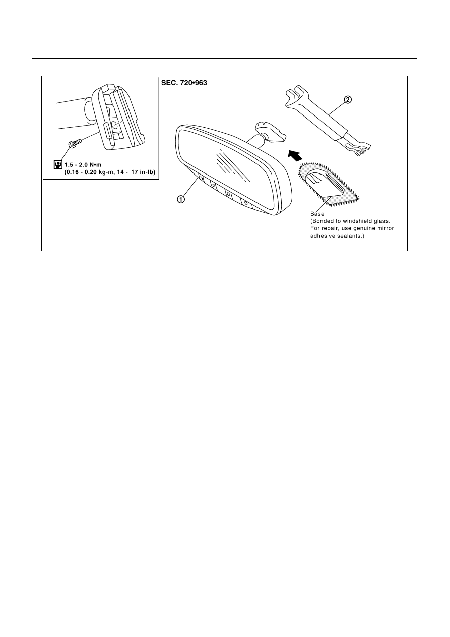
CAUTION:
Apply Genuine Mirror Adhesive or equivalent to bonding surface of mounting bracket. Refer to
"RECOMMENDED CHEMICAL PRODUCTS AND SEALANTS"
REMOVAL
1.
Remove inside mirror finisher (if equipped).
2.
Remove screw of mirror base.
3.
Slide the mirror upward to remove.
4.
Disconnect the connector (if equipped).
INSTALLATION
Install in the reverse order of removal.
1.
Inside mirror
2.
Inside mirror finisher (if equipped)
PIIA9845E