Nissan Murano Z50 (2004 year). Manual - part 123
FRONT DRIVE SHAFT
FAX-15
C
E
F
G
H
I
J
K
L
M
A
B
FAX
Revision: 2004 November
2004 Murano
8.
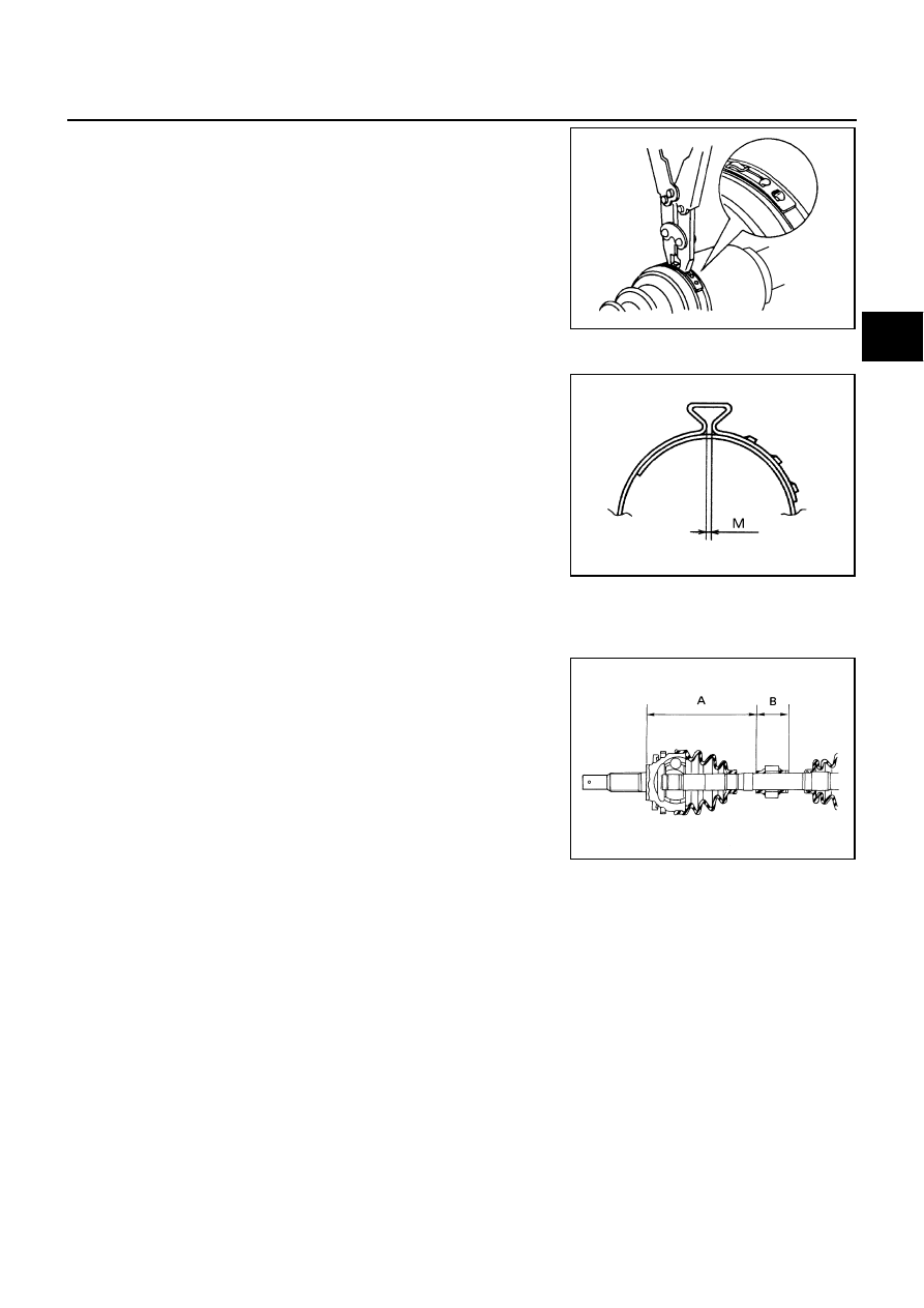
Install new larger and smaller boot bands securely with a suit-
able tool.
CAUTION:
●
Secure boot band so that dimension “M” shown at left
satisfies the following:
9.
After installing housing and shaft, rotate boot to check whether or not the actual position is correct. If boot
position is not correct, secure boot with new boot bands again.
Damper
1.
Use new damper bands when installing.
2.
Install damper from stationary-joint side while holding it securely.
RAC1133D
Dimension “M”
: 1.0 - 4.0 mm (0.039 - 0.157 in)
DSF0047D
“A”
: 207 - 213 mm (8.15 - 8.39 in)
“B”
: 70 mm (2.76 in)
SFA313B