Nissan Murano Z50 (2004 year). Manual - part 113


  Index      Manuals     Nissan Murano Z50 (2004 year) - Service and Repair Manual


Search            copyright infringement  


Content      ..     111      112      113      114     ..


Nissan Murano Z50 (2004 year). Manual - part 113


DRIVE BELTS

EM-11

C

D

E

F

G

H

I

J

K

L

M

A

EM

Revision: 2004 November

2004 Murano

DRIVE BELTS

PFP:02117

Checking Drive Belts

ABS00329

WARNING:

Be sure to perform when the engine is stopped.
1.

Inspect belts for cracks, fraying, wear and oil. If necessary, replace.

2.

Inspect drive belt deflection or tension at a point on belt midway
between pulleys.

Inspection should be done only when engine is cold, or over
30 minutes after engine is stopped.

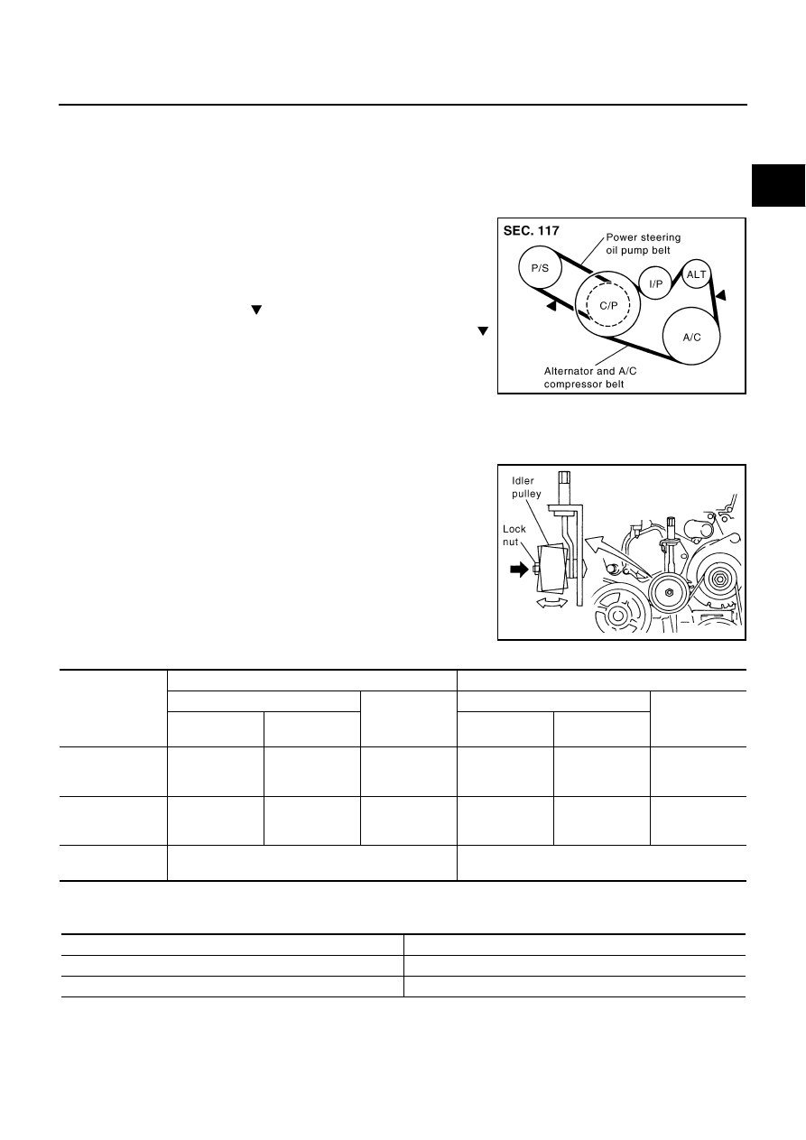
Measure belt tension with tension gauge (BT3373-F or equiv-
alent) at points marked   shown in the figure.

When measuring deflection, apply 98 N (10 kg, 22 lb) at the 
marked point.

Adjust if belt deflection exceeds the limit or if belt tension is
not within specifications.

CAUTION:

When checking belt deflection or tension immediately after installation, first adjust it to the
specified value. Then, after turning the crankshaft two turns or more, re-adjust to the specified
value to avoid variation in deflection between pulleys.

Tighten idler pulley lock nut by hand and measure deflec-
tion or tension without looseness.

Belt Deflection and Tension

*: If belt tension gauge cannot be installed at check points shown, check drive belt tension at different location on the belt.

Tension Adjustment

ABS0036V

CAUTION:

When belt is replaced with a new one, adjust it to value for “New belt” to accommodate for insuffi-
cient adaptability with pulley grooves.

PBIC2449E

PBIC1162E

Deflection adjustment

Unit: mm (in)

Tension adjustment*

Unit: mm (in)

Used belt

New belt

Used belt

New belt

Limit

After adjustment

Limit

 After adjust-

ment

Alternator and A/C 
compressor

       7 (0.28)

       4.2 - 4.6
    (0.17 - 0.18)

      3.7 - 4.1
   (0.15 - 0.16)

294 (30, 66)

730 - 818

(74.5 - 83.5,

164 - 184)

838 - 926

(85.5 - 94.5,

188 - 208)

Power steering oil 
pump

      11 (0.43)

        7.3 - 8
    (0.29 - 0.30)

      6.5 - 7.2
   (0.26 - 0.28)

196 (20, 44)

495 - 583

(50.5 - 59.5,

111 - 131)

603 - 691

(61.5 - 70.5, 

135.6 - 155.4)

Applied pushing 
force

                             98 N (10 Kg, 22 lb)

                                            —

Portion

Belt tightening method for adjustment

Power steering oil pump belt

Adjusting bolt on power steering oil pump

Alternator and air conditioner compressor belt

Adjusting bolt on idler pulley

EM-12

DRIVE BELTS

Revision: 2004 November

2004 Murano

When deflection or tension of belt being used exceeds “Limit”, adjust it to value for “After adjust-
ment”.

When checking belt deflection or tension immediately after installation, first adjust it to the speci-
fied value. Then, after turning the crankshaft two turns or more, re-adjust to the specified value to
avoid variation in deflection between pulleys.

When installing belt, make sure that it is correctly engaged with pulley groove.

Keep engine oil, working fluid and engine coolant away from belt.

Do not twist or bend belt excessively.

ALTERNATOR AND AI/C COMPRESSOR BELT

1.

Remove splash guard (RH).

2.

Loosen idler pulley lock nut (A) and adjust tension by turning
adjusting nut (B).

For specified belt tension, refer to 

EM-11, "Checking Drive

Belts"

 .

3.

Tighten lock nut (A).

4.

Tighten adjusting nut (B).

POWER STEERING OIL PUMP BELT

1.

Remove splash guard (RH).

2.

Loosen lock bolt (C).

3.

Loosen power steering oil pump mounting bolt (D).

Bolt head (D) is engine rear side.

4.

Adjust tension by turning adjusting bolt (E).

For specified belt tension, refer to 

EM-11, "Checking Drive Belts"

 .

NOTE:
Adjusting bolt (E) is loosened with counterclockwise rotation.

5.

Tighten lock bolt (C).

6.

Tighten power steering oil pump mounting bolt (D).

Removal and Installation

ABS0036W

REMOVAL

1.

Remove splash guard (RH).

2.

Fully loosen each belt by following the guidelines in 

EM-11, "Tension Adjustment"

 . Remove alternator and

A/C compressor belt and then power steering oil pump belt.


 : 34.8 N·m (3.5 kg-m, 26 ft-lb)


 : 5.4 N·m (0.55 kg-m, 48 in-lb)

PBIC2450E

 : 28.0 N·m (2.9 kg-m, 21 ft-lb)

 : 43.2 N·m (4.4 kg-m, 32 ft-lb)

DRIVE BELTS

EM-13

C

D

E

F

G

H

I

J

K

L

M

A

EM

Revision: 2004 November

2004 Murano

CAUTION:

Grease is applied to idler pulley adjusting bolt. Be careful to keep grease away from belt.

INSTALLATION

1.

Install each belt to pulley in the reverse order of removal.

CAUTION:

Make sure belt is correctly engaged with the pulley groove.

Make sure that for engine oil, working fluid and engine coolant do not adhere to belt and each
pulley groove.

2.

Adjust belt tension. Refer to 

EM-11, "Tension Adjustment"

 .

3.

Tighten each nuts and bolts to the specified torque.

4.

Make sure that tension of each belt is within the standard. Refer to 

EM-11, "Checking Drive Belts"

 .

EM-14

AIR CLEANER AND AIR DUCT

Revision: 2004 November

2004 Murano

AIR CLEANER AND AIR DUCT

PFP:16500

Removal and Installation

ABS0033C

REMOVAL

1.

Remove radiator cover grills (right and left side).

2.

Remove air duct (inlet).

3.

Disconnect harness connector from mass air flow sensor.

4.

Disconnect PCV hose.

5.

Remove air cleaner cases (upper and lower) with mass air flow sensor and air duct assembly disconnect-
ing their joints.

Add mating marks as necessary for easier installation.

6.

Remove mass air flow sensor from air cleaner case (upper), as necessary.

CAUTION:

Handle mass air flow sensor with following cares.

Do not shock it.

Do not disassemble it.

Do not touch its sensor.

1.

Air cleaner case (lower)

2.

Air cleaner filter

3.

Air cleaner case (upper)

4.

Air duct assembly

5.

Harness bracket

6.

Mass air flow sensor

7.

O-ring

8.

PCV hose

9.

Clip

10. Radiator cover grill (right side)

11. Air duct (inlet)

12.

Radiator cover grill (left side)

13. Resonator

14. Bracket

15.

Grommet

16. Bracket

PBIC1806E

AIR CLEANER AND AIR DUCT

EM-15

C

D

E

F

G

H

I

J

K

L

M

A

EM

Revision: 2004 November

2004 Murano

7.

Remove resonator, removing left side fender protector (front), as necessary.

INSPECTION AFTER REMOVAL

Inspect air duct assembly for crack or tear.

If anything found, replace air duct assembly.

INSTALLATION

Note the following, and install in the reverse order of removal.

Align marks. Attach each joint. Screw clamps firmly.

Changing Air Cleaner Filter

ABS00BYS

REMOVAL

1.

Unhook air cleaner case (lower) side clips and lift up air cleaner case (upper).

2.

Remove air cleaner filter.

INSTALLATION

Install in the reverse order of removal.

PBIC1165E

EM-16

INTAKE MANIFOLD COLLECTOR

Revision: 2004 November

2004 Murano

INTAKE MANIFOLD COLLECTOR

PFP:14003

Removal and Installation

ABS00FPR

1.

Electric throttle control actuator

2.

Gasket

3.

Intake manifold collector (upper)

4.

PCV hose

5.

Harness bracket

6.

Gasket

7.

Power valve

8.

VIAS control solenoid valve

9.

Vacuum tank

10. Gasket

11. Intake manifold collector (lower)

12.

EVAP canister purge volume control 
solenoid valve

13. Gasket

14. EVAP hose

15. Purge resonator

16. Service port

17. Fuel hose

18. Intake manifold collector support

PBIC1906E

INTAKE MANIFOLD COLLECTOR

EM-17

C

D

E

F

G

H

I

J

K

L

M

A

EM

Revision: 2004 November

2004 Murano

REMOVAL

WARNING:

To avoid the danger of being scalded, never drain engine coolant when engine is hot.
1.

Remove engine cover.

CAUTION:

Be careful not to damage or scratch engine cover.

2.

Remove air cleaner case (upper) with mass air flow sensor and air duct assembly. Refer to 

EM-14, "AIR

CLEANER AND AIR DUCT"

 .

3.

Drain engine coolant, or when water hoses are disconnected, attach plug to prevent engine coolant leak-
age. Refer to 

CO-9, "Changing Engine Coolant"

 .

CAUTION:

Perform when engine is cold.

4.

Remove electric throttle control actuator as follows:

a.

Disconnect harness connector.

b.

Loosen mounting bolts in reverse order as shown in the figure.

CAUTION:

Handle carefully to avoid any shock to electric throttle
control actuator.

Do not disassemble.

5.

Disconnect water hoses from intake manifold collector (upper).

When engine coolant is not drained from radiator, attach plug to water hoses to prevent engine coolant
leakage.

PBIC1910E

KBIA2007J

EM-18

INTAKE MANIFOLD COLLECTOR

Revision: 2004 November

2004 Murano

6.

Remove the following parts:

Vacuum hose

PCV hose

Power steering hose bracket

Intake manifold collector support

Harness bracket

7.

Disconnect EVAP hoses and harness connector from EVAP canister purge volume control solenoid valve.

8.

Remove EVAP canister purge volume control solenoid valve.

9.

Remove VIAS control solenoid valve and vacuum tank.

Add mating marks as necessary for easier installation. 

10. Loosen mounting nuts and bolts in reverse order as shown in

the figure with power tool, and remove intake manifold collector
(upper and lower) assembly and gasket.

CAUTION:

Cover engine openings to avoid entry of foreign materials.

11. Loosen mounting bolts in reverse order as shown in the figure to

remove intake manifold collector (upper) from intake manifold
collector (lower) with power tool.

12. Loosen mounting bolts in reverse order as shown in the figure to

remove power valve from intake manifold collector (lower).

PBIC2455E

SEM713G

SEM712G

SEM714G

INTAKE MANIFOLD COLLECTOR

EM-19

C

D

E

F

G

H

I

J

K

L

M

A

EM

Revision: 2004 November

2004 Murano

INSPECTION AFTER REMOVAL
Surface Distortion

Check the surface distortion of intake manifold collector (lower)
with straightedge and feeler gauge.

If it exceeds the limit, replace intake manifold collector (lower).

INSTALLATION

Note the following, and install in the reverse order of removal.

Power Valve

Tighten mounting bolts in numerical order as shown in the figure.

Intake Manifold Collector (Upper)

Tighten mounting bolts in numerical order as shown in the figure.

Intake Manifold Collector (Lower)

Tighten mounting nuts and bolts in numerical order as shown in the
figure.

Electric Throttle Control Actuator

Install gasket with positioning no-protrusion surface upward or downward.

Limit

: 0.1 mm (0.004 in)

PBIC1168E

SEM714G

SEM712G

SEM713G

EM-20

INTAKE MANIFOLD COLLECTOR

Revision: 2004 November

2004 Murano

Tighten mounting bolts in numerical order as shown in the fig-
ure.

Perform the “Throttle Valve Closed Position Learning” when har-
ness connector of electric throttle control actuator is discon-
nected. Refer to 

EC-43, "Throttle Valve Closed Position

Learning"

 .

Perform the “Idle Air Volume Learning” and “Throttle Valve
Closed Position Learning” when electric throttle control actuator
is replaced. Refer to 

EC-43, "Idle Air Volume Learning"

 .

KBIA2007J

INTAKE MANIFOLD

EM-21

C

D

E

F

G

H

I

J

K

L

M

A

EM

Revision: 2004 November

2004 Murano

INTAKE MANIFOLD

PFP:14003

Removal and Installation

ABS0033D

REMOVAL

1.

Release fuel pressure. Refer to 

EC-45, "FUEL PRESSURE RELEASE"

 .

2.

Remove intake manifold collectors (upper and lower). Refer to 

EM-16, "INTAKE MANIFOLD COLLEC-

TOR"

 .

3.

Remove fuel tube and fuel injector assembly. Refer to 

EM-40, "FUEL INJECTOR AND FUEL TUBE"

 .

4.

Loosen mounting nuts and bolts in reverse order as shown in
the figure to remove intake manifold with power tool.

5.

Remove gaskets.

CAUTION:

Cover engine openings to avoid entry of foreign materials.

INSPECTION AFTER REMOVAL
Surface Distortion

Check the surface distortion of the intake manifold mating sur-
faces with straightedge and feeler gauge.

If it exceeds the limit, replace intake manifold.

1.

Intake manifold

2.

Gasket

PBIC2458E

PBIC0778E

Limit

: 0.1 mm (0.004 in)

PBIC0870E

EM-22

INTAKE MANIFOLD

Revision: 2004 November

2004 Murano

INSTALLATION

Note the following, and install in the reverse order or removal.

Intake Manifold

If stud bolts were removed, install them and tighten to the specified torque below.

Tighten all mounting nuts and bolts to the specified torque in two
or more steps in numerical order shown in figure.

 : 9.8 - 11.8 N·m (1.0 - 1.2 kg-m, 87 - 104 in-lb)

 1st step

: 4.9 - 9.8 N·m (0.5 - 1.0 kg-m, 4 - 7 ft-lb)

 2nd step and after

: 26.5 - 31.4 N·m (2.7 - 3.2 kg-m, 20 - 23 ft-lb)

PBIC0778E

EXHAUST MANIFOLD AND THREE WAY CATALYST

EM-23

C

D

E

F

G

H

I

J

K

L

M

A

EM

Revision: 2004 November

2004 Murano

EXHAUST MANIFOLD AND THREE WAY CATALYST

PFP:14004

Removal and Installation

ABS0032G

REMOVAL

WARNING:

Perform the work when the exhaust and cooling system have completely cooled down.

When removing engine mounting through bolts and nuts, lift the engine up slightly for safety with
transmission jack.  Refer to 

EM-105, "ENGINE ASSEMBLY"

 .

1.

Drain engine coolant. Refer to 

CO-9, "Changing Engine Coolant"

 .

CAUTION:

Perform this step when engine is cold.

Do not spill engine coolant on drive belts.

2.

Remove following parts:

Engine cover; Refer to 

EM-16, "INTAKE MANIFOLD COLLECTOR"

 .

Radiator cover grilles, air duct (inlet), air cleaner cases (upper) with mass air flow sensor and air duct
assembly; Refer to 

EM-14, "AIR CLEANER AND AIR DUCT"

 .

1.

Air fuel ratio sensor 1 (bank 1)

2.

Exhaust manifold cover (right bank)

3.

Exhaust manifold (right bank)

4.

Ring gasket

5.

Three way catalyst (right bank)

6.

Three way catalyst support (right 
bank)

7.

Heated oxygen sensor 2 (bank 1)

8.

Gasket

9.

Gasket

10. Air fuel ratio sensor 1 (bank 2)

11. Three way catalyst (left bank)

12. Three way catalyst cover

13. Three way catalyst cover

14. Three way catalyst cover

15.

Three way catalyst support (left 
bank)

16. Heated oxygen sensor 2  (bank 2)

17. Exhaust manifold cover (left bank)

18. Exhaust manifold (left bank)

PBIC2461E

EM-24

EXHAUST MANIFOLD AND THREE WAY CATALYST

Revision: 2004 November

2004 Murano

Undercover

Radiator and radiator cooling fan assembly; Refer to 

CO-13, "RADIATOR"

 .

3.

Remove exhaust front tube mounting bracket and then remove exhaust front tube.Refer to 

EX-3,

"EXHAUST SYSTEM"

 .

4.

Remove front wiper arm (RH) and cowl top cover (right) (when RH exhaust manifold and three way cata-
lyst is removed). Refer to 

WW-4, "FRONT WIPER AND WASHER SYSTEM"

 an

EI-21, "COWL TOP"

 .

5.

Remove heat insulator.

6.

Support the transaxle bottom with jack. (AWD models) (when RH exhaust manifold and three way catalyst
is removed)

CAUTION:

Put a peace of wood or something similar as the supporting surface, be careful not to damage
transaxle.

7.

Remove rear engine mounting insulator. (AWD models) Refer to 

EM-105, "ENGINE ASSEMBLY"

 .

8.

Disconnect harness connector and remove air fuel ratio sensor
1 on both banks with heated oxygen sensor wrench [SST].

Put marks to identify installation positions of each air fuel ratio
sensor 1.

CAUTION:

Be careful not to damage air fuel ratio sensor 1.

Discard any air fuel ratio sensor 1 which has been
dropped from a height of more than 0.5 m (19.7 in) onto a
hard surface such as a concrete floor; replace with a new
sensor.

NOTE:
Figure is shown as an example of left bank.

9.

Disconnect harness connector and remove heated oxygen sen-
sor 2 on both banks with heated oxygen sensor wrench [SST].

Put marks to identify installation positions of each heated oxy-
gen sensor 2.

CAUTION:

Be careful not to damage heated oxygen sensor 2.

Discard any heated oxygen sensor 2 which has been
dropped from a height of more than 0.5 m (19.7 in) onto a
hard surface such as a concrete floor; replace with a new
sensor.

10. Remove exhaust manifold covers (right and left banks) and three way catalyst covers.

PBIC2503E

PBIC2674E

PBIC2675E

EXHAUST MANIFOLD AND THREE WAY CATALYST

EM-25

C

D

E

F

G

H

I

J

K

L

M

A

EM

Revision: 2004 November

2004 Murano

11. Remove mounting bolts in reverse order as shown in the figure

to remove three way catalyst supports (right and left banks).

12. Remove three way catalysts (right and left banks) by loosening bolts first and then removing nuts.

CAUTION:

Handle carefully to avoid any shock to three way catalyst.

13. Loosen mounting nuts in reverse order as shown in the figure to

remove exhaust manifolds (right and left banks).

14. Remove gaskets.

CAUTION:

Cover engine openings to avoid entry of foreign materials.

INSPECTION AFTER REMOVAL
Surface Distortion

Check the surface distortion of the exhaust manifold mating sur-
faces with straightedge and feeler gauge.

If it exceeds the limit, replace exhaust manifold.

INSTALLATION

Note the following, and install in the reverse order of removal.

PBIC2463E

PBIC2464E

Limit

: 0.3 mm (0.012 in)

PBIC1173E

EM-26

EXHAUST MANIFOLD AND THREE WAY CATALYST

Revision: 2004 November

2004 Murano

Exhaust Manifold Gasket

Install in the direction indicated in the figure.

Exhaust Manifold

If stud bolts were removed, install them and tighten to the torque specified below.

Tighten mounting nuts in numerical order as shown in the figure.

Three Way Catalyst Supports

1.

Temporarily tighten three way catalyst support mounting bolts.

2.

Tighten three way catalyst support mounting bolts to specified
torque in numerical order as shown in the figure.

Air Fuel Ratio Sensor 1 and Heated Oxygen Sensor 2

Install air fuel ratio sensor 1 and heated oxygen sensor 2 in the original position.

KBIA1051E

 : 14.2 - 16.6 N·m (1.5 - 1.6 kg-m, 11 - 12ft-lb)

PBIC2464E

PBIC2463E


Content      ..     111      112      113      114     ..