Nissan Murano Z50 (2004 year). Manual - part 95
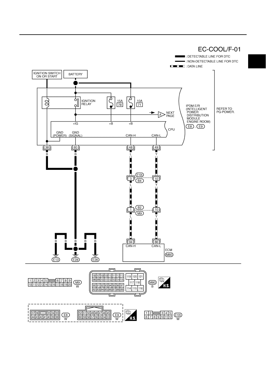
DTC P1217 ENGINE OVER TEMPERATURE
EC-431
C
D
E
F
G
H
I
J
K
L
M
A
EC
Revision: 2004 November
2004 Murano
Wiring Diagram
ABS004L7
TBWA0712E
|
|
|
DTC P1217 ENGINE OVER TEMPERATURE EC-431 C D E F G H I J K L M A EC Revision: 2004 November 2004 Murano Wiring Diagram ABS004L7 TBWA0712E |