Nissan Murano Z50 (2004 year). Manual - part 88
DTC P0453 EVAP CONTROL SYSTEM PRESSURE SENSOR
EC-319
C
D
E
F
G
H
I
J
K
L
M
A
EC
Revision: 2004 November
2004 Murano
DTC Confirmation Procedure
ABS004HE
NOTE:
If DTC Confirmation Procedure has been previously conducted, always turn ignition switch OFF and wait at
least 10 seconds before conducting the next test.
TESTING CONDITION:
Always perform test at a temperature of 5
°
C (41
°
F) or more.
WITH CONSULT-II
1.
Start engine and warm it up to normal operating temperature.
2.
Turn ignition switch OFF and wait at least 10 seconds.
3.
Turn ignition switch ON.
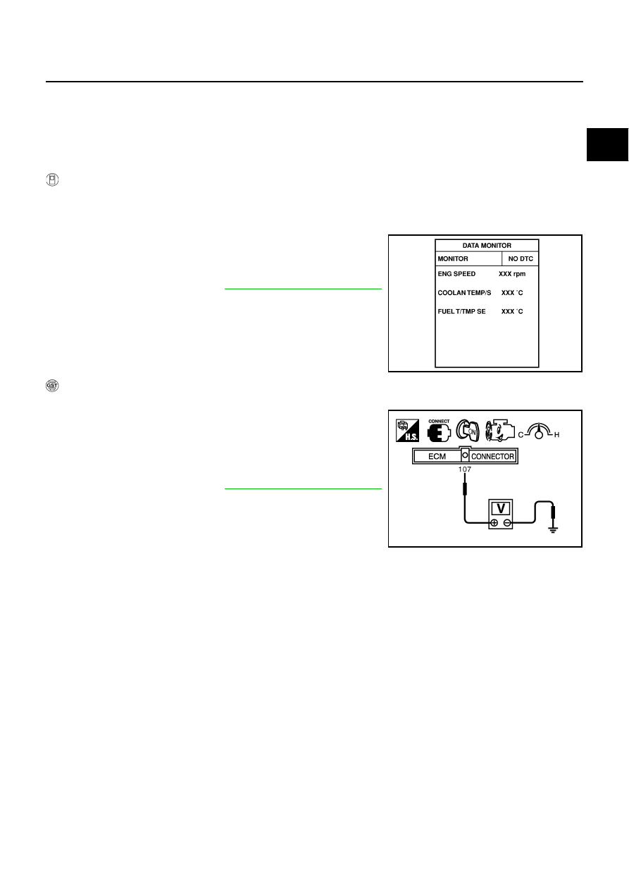
4.
Select “DATA MONITOR” mode with CONSULT-II.
5.
Make sure that “FUEL T/TEMP SE” is more than 0
°
C (32
°
F).
6.
Wait at least 10 seconds.
7.
If 1st trip DTC is detected, go to
EC-321, "Diagnostic Procedure"
.
WITH GST
1.
Start engine and warm it up to normal operating temperature.
2.
Check that voltage between ECM terminal 107 (Fuel tank tem-
perature sensor signal) and ground is less than 4.2V.
3.
Turn ignition switch OFF and wait at least 10 seconds.
4.
Turn ignition switch ON and wait at least 10 seconds.
5.
Select MODE 7 with GST.
If 1st trip DTC is detected, go to
EC-321, "Diagnostic Procedure"
.
SEF194Y
PBIB1110E