Nissan Murano Z50 (2004 year). Manual - part 84


  Index      Manuals     Nissan Murano Z50 (2004 year) - Service and Repair Manual


Search            copyright infringement  


Content      ..     82      83      84      85     ..


Nissan Murano Z50 (2004 year). Manual - part 84


DTC P0300 - P0306 MULTIPLE CYLINDER MISFIRE, NO. 1 - 6 CYLINDER MIS-

FIRE

EC-255

C

D

E

F

G

H

I

J

K

L

M

A

EC

Revision: 2004 November

2004 Murano

11. 

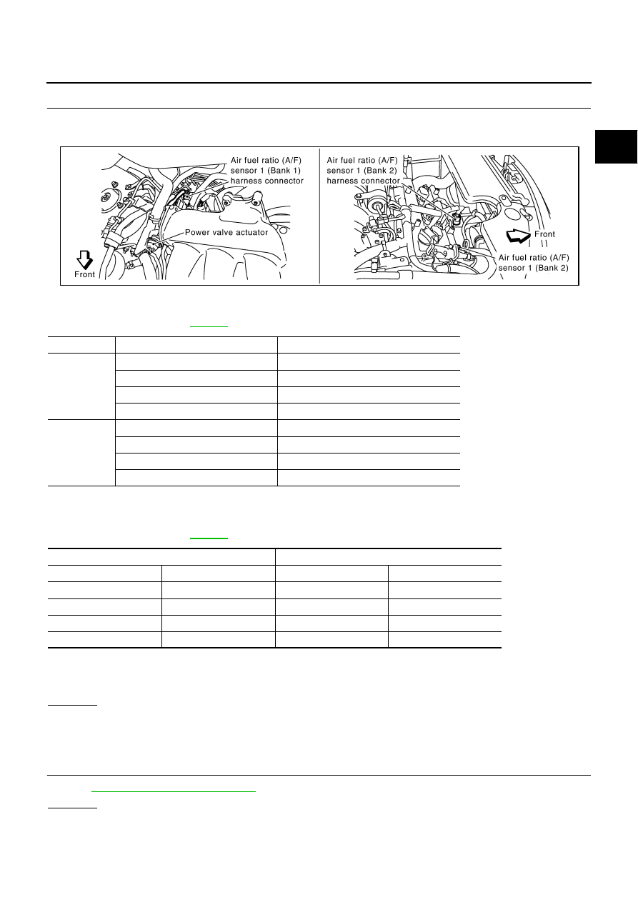
CHECK A/F SENSOR 1 INPUT SIGNAL

1.

 Turn ignition switch OFF.

2.

Disconnect A/F sensor 1 harness connector.

3.

Disconnect ECM harness connector.

4.

Check harness continuity between the following terminals.
Refer to Wiring Diagram

EC-451

 .

5.

Check harness continuity between the following terminals and ground.
Refer to Wiring Diagram

EC-451

 .

6.

Also check harness for short to power.

OK or NG

OK

>> GO TO 12.

NG

>> Repair open circuit or short to ground or short to power in harness or connectors between ECM

and A/F sensor 1.

12. 

CHECK A/F SENSOR 1 HEATER

Refer to 

EC-372, "Component Inspection"

 .

OK or NG

OK

>> GO TO 13.

NG

>> Replace (malfunctioning) A/F sensor 1.

ECM terminal

A/F sensor 1 terminal

Bank 1

16

1

35

5

56

6

75

2

Bank 2

76

1

57

5

58

6

77

2

Continuity should exist.

Bank 1

Bank 2

ECM terminal

A/F sensor 1 terminal

ECM terminal

A/F sensor 1 terminal

16

1

76

1

35

5

57

5

56

6

58

6

75

2

77

2

Continuity should not exist.

PBIB2293E

EC-256

DTC P0300 - P0306 MULTIPLE CYLINDER MISFIRE, NO. 1 - 6 CYLINDER MIS-

FIRE

Revision: 2004 November

2004 Murano

13. 

CHECK MASS AIR FLOW SENSOR

 With CONSULT-II

Check mass air flow sensor signal in “DATA MONITOR” mode with CONSULT-II.

 With GST

Check mass air flow sensor signal in MODE 1 with GST.

OK or NG

OK

>> GO TO 14.

NG

>> Check connectors for rusted terminals or loose connections in the mass air flow sensor circuit or

grounds. Refer to 

EC-155, "DTC P0101 MAF SENSOR"

 .

14. 

CHECK SYMPTOM MATRIX CHART

Check items on the rough idle symptom in 

EC-83, "Symptom Matrix Chart"

 .

OK or NG

OK

>> GO TO 15.

NG

>> Repair or replace.

15. 

ERASE THE 1ST TRIP DTC

Some tests may cause a 1st trip DTC to be set.
Erase the 1st trip DTC from the ECM memory after performing the tests. Refer to 

EC-61, "HOW TO ERASE

EMISSION-RELATED DIAGNOSTIC INFORMATION"

 .

>> GO TO 16.

16. 

CHECK INTERMITTENT INCIDENT

Refer to 

EC-130, "TROUBLE DIAGNOSIS FOR INTERMITTENT INCIDENT"

 .

>> INSPECTION END

2.0 - 6.0 g·m/sec:

at idling

7.0 - 20.0 g·m/sec:

at 2,500 rpm

2.0 - 6.0 g·m/sec:

at idling

7.0 - 20.0 g·m/sec:

at 2,500 rpm

DTC P0327, P0328 KS

EC-257

C

D

E

F

G

H

I

J

K

L

M

A

EC

Revision: 2004 November

2004 Murano

DTC P0327, P0328 KS

PFP:22060

Component Description

ABS004FR

The knock sensor is attached to the cylinder block. It senses engine
knocking using a piezoelectric element. A knocking vibration from
the cylinder block is sensed as vibrational pressure. This pressure is
converted into a voltage signal and sent to the ECM.

On Board Diagnosis Logic

ABS004FS

The MIL will not light up for these diagnoses.

DTC Confirmation Procedure

ABS004FT

NOTE:
If DTC Confirmation Procedure has been previously conducted, always turn ignition switch OFF and wait at
least 10 seconds before conducting the next test.
TESTING CONDITION:
Before performing the following procedure, confirm that battery voltage is more than 10V at idle.

 WITH CONSULT-II

1.

Turn ignition switch ON and select “DATA MONITOR” mode with
CONSULT-II.

2.

Start engine and run it for at least 5 seconds at idle speed.

3.

If 1st trip DTC is detected, go to 

EC-259, "Diagnostic Procedure"

.

 WITH GST

Follow the procedure “WITH CONSULT-II” above.

PBIB1359E

DTC No.

Trouble diagnosis 

name

DTC detected condition

Possible cause

P0327
0327

Knock sensor circuit 
low input

An excessively low voltage from the sensor is 
sent to ECM.

Harness or connectors
(The sensor circuit is open or shorted.)

Knock sensor

P0328
0328

Knock sensor circuit 
high input

An excessively high voltage from the sensor is 
sent to ECM.

SEF058Y

EC-258

DTC P0327, P0328 KS

Revision: 2004 November

2004 Murano

Wiring Diagram

ABS004FU

TBWA0700E

DTC P0327, P0328 KS

EC-259

C

D

E

F

G

H

I

J

K

L

M

A

EC

Revision: 2004 November

2004 Murano

Specification data are reference values and are measured between each terminal and ground.

CAUTION:

Do not use ECM ground terminals when measuring input/output voltage. Doing so may result in dam-
age to the ECM's transistor. Use a ground other than ECM terminals, such as the ground.

Diagnostic Procedure

ABS004FV

1. 

CHECK KNOCK SENSOR INPUT SIGNAL CIRCUIT FOR OPEN AND SHORT-I

1.

Turn ignition switch OFF.

2.

Disconnect ECM harness connector.

3.

Check resistance between ECM terminal 15 and ground. Refer to Wiring Diagram.

NOTE:
It is necessary to use an ohmmeter which can measure more than 10 M

.

4.

Also check harness for short to ground and short to power.

OK or NG

OK

>> GO TO 4.

NG

>> GO TO 2.

2. 

CHECK KNOCK SENSOR INPUT SIGNAL CIRCUIT FOR OPEN AND SHORT-II

1.

Disconnect knock sensor harness connector.

2.

Check harness continuity between ECM terminal 15 and knock
sensor terminal 1. 
Refer to Wiring Diagram.

3.

Also check harness for short to ground and short to power.

OK or NG

OK

>> GO TO 4.

NG

>> GO TO 3.

3. 

DETECT MALFUNCTIONING PART

Check the following.

Harness connectors F9, F241

Harness for open or short between ECM and knock sensor

>> Repair open circuit or short to ground or short to power in harness or connectors.

4. 

CHECK KNOCK SENSOR

Refer to 

EC-261, "Component Inspection"

 .

OK or NG

OK

>> GO TO 5.

NG

>> Replace knock sensor.

TER-

MINAL 

NO.

WIRE 

COLOR

ITEM

CONDITION

DATA (DC Voltage)

15

W

Knock sensor

[Engine is running]

Idle speed

Approximately 2.5V

Resistance: Approximately 532 - 588 k

 [at 20

°

C (68

°

F)]

Continuity should exist.

PBIB1359E

EC-260

DTC P0327, P0328 KS

Revision: 2004 November

2004 Murano

5. 

CHECK GROUND CONNECTIONS

1.

Turn ignition switch OFF.

2.

Loosen and retighten two ground screws on the body.
Refer to 

EC-139, "Ground Inspection"

 .

OK or NG

OK

>> GO TO 6.

NG

>> Repair or replace ground connections.

6. 

CHECK KNOCK SENSOR SHIELD CIRCUIT FOR OPEN AND SHORT

1.

Disconnect knock sensor harness connector.

2.

Check harness continuity between knock sensor terminal 2 and ground. Refer to Wiring Diagram.

3.

Also check for short to power.

OK or NG

OK

>> GO TO 8.

NG

>> GO TO 7.

7. 

DETECT MALFUNCTIONING PART

Check the following.

Harness connectors F9, F241

Harness connectors F102, M82

Harness for open or short between knock sensor terminal 2 and ground

>> Repair open circuit or short power in harness or connectors.

8. 

CHECK INTERMITTENT INCIDENT

Refer to 

EC-130, "TROUBLE DIAGNOSIS FOR INTERMITTENT INCIDENT"

 .

>> INSPECTION END

PBIB1835E

Continuity should exist.

DTC P0327, P0328 KS

EC-261

C

D

E

F

G

H

I

J

K

L

M

A

EC

Revision: 2004 November

2004 Murano

Component Inspection

ABS004FW

KNOCK SENSOR

Check resistance between knock sensor terminal 1 and ground.

NOTE:
It is necessary to use an ohmmeter which can measure more
than 10 M

.

CAUTION:

Do not use any knock sensors that have been dropped or phys-
ically damaged. Use only new ones.

Removal and Installation

ABS004FX

KNOCK SENSOR

Refer to 

EM-110, "CYLINDER BLOCK"

 .

Resistance: Approximately 532 - 588 k

 [at 20

°

C (68

°

F)]

SEF111Y

EC-262

DTC P0335 CKP SENSOR (POS)

Revision: 2004 November

2004 Murano

DTC P0335 CKP SENSOR (POS)

PFP:23731

Component Description

ABS004FY

The crankshaft position sensor (POS) is located on the oil pan facing
the gear teeth (cogs) of the signal plate. It detects the fluctuation of
the engine revolution.
The sensor consists of a permanent magnet and Hall IC.
When the engine is running, the high and low parts of the teeth
cause the gap with the sensor to change.
The changing gap causes the magnetic field near the sensor to
change.
Due to the changing magnetic field, the voltage from the sensor
changes.
The ECM receives the voltage signal and detects the fluctuation of
the engine revolution.

CONSULT-II Reference Value in Data Monitor Mode

ABS004FZ

Specification data are reference values.

On Board Diagnosis Logic

ABS004G0

DTC Confirmation Procedure

ABS004G1

NOTE:
If DTC Confirmation Procedure has been previously conducted, always turn ignition switch OFF and wait at
least 10 seconds before conducting the next test.
TESTING CONDITION:
Before performing the following procedure, confirm that battery voltage is more than 10.5V with igni-
tion switch “ON”.

 WITH CONSULT-II

1.

Turn ignition switch ON and select “DATA MONITOR” mode with
CONSULT-II.

2.

Crank engine for at least 2 seconds and run it for at least 5 sec-
onds at idle speed.

3.

If 1st trip DTC is detected, go to 

EC-264, "Diagnostic Procedure"

.

 WITH GST

Follow the procedure “WITH CONSULT-II” above.

PBIB0562E

MONITOR ITEM 

CONDITION

SPECIFICATION 

ENG SPEED

Run engine and compare CONSULT-II value with the tachometer indica-
tion.

Almost the same speed as the 
tachometer indication. 

DTC No.

Trouble diagnosis name

DTC detecting condition

Possible cause

P0335
0335

Crankshaft position 
sensor (POS) circuit

The crankshaft position sensor (POS) signal 
is not detected by the ECM during the first 
few seconds of engine cranking.

The proper pulse signal from the crankshaft 
position sensor (POS) is not sent to ECM 
while the engine is running.

The crankshaft position sensor (POS) signal 
is not in the normal pattern during engine 
running.

Harness or connectors
(The sensor circuit is open or shorted)

Crankshaft position sensor (POS)

Signal plate

SEF058Y

DTC P0335 CKP SENSOR (POS)

EC-263

C

D

E

F

G

H

I

J

K

L

M

A

EC

Revision: 2004 November

2004 Murano

Wiring Diagram

ABS004G2

TBWA0701E

EC-264

DTC P0335 CKP SENSOR (POS)

Revision: 2004 November

2004 Murano

Specification data are reference values and are measured between each terminal and ground.
Pulse signal is measured by CONSULT-II.

CAUTION:

Do not use ECM ground terminals when measuring input/output voltage. Doing so may result in dam-
age to the ECM's transistor. Use a ground other than ECM terminals, such as the ground.

: Average voltage for pulse signal (Actual pulse signal can be confirmed by oscilloscope.)

Diagnostic Procedure

ABS004G3

1. 

CHECK GROUND CONNECTIONS

1.

Turn ignition switch OFF.

2.

Loosen and retighten two ground screws on the body.
Refer to 

EC-139, "Ground Inspection"

 .

OK or NG

OK

>> GO TO 2.

NG

>> Repair or replace ground connections.

TER-

MINAL 

NO.

WIRE 

COLOR

ITEM

CONDITION

DATA (DC Voltage)

13

W

Crankshaft position sensor 
(POS)

[Engine is running]

Warm-up condition

Idle speed

NOTE:
The pulse cycle changes depending on rpm at 
idle

Approximately 1.6V

[Engine is running]

Engine speed is 2,000 rpm.

Approximately 1.4V

PBIB1041E

PBIB1042E

PBIB1835E

DTC P0335 CKP SENSOR (POS)

EC-265

C

D

E

F

G

H

I

J

K

L

M

A

EC

Revision: 2004 November

2004 Murano

2. 

CHECK CRANKSHAFT POSITION (CKP) SENSOR (POS) POWER SUPPLY CIRCUIT

1.

Disconnect crankshaft position (CKP) sensor (POS) harness connector.

2.

Turn ignition switch ON.

3.

Check voltage between CKP sensor (POS) terminal 1 and
ground with CONSULT-II or tester.

4.

Also check harness for short to ground and short to power.

OK or NG

OK

>> GO TO 4.

NG

>> GO TO 3.

3. 

DETECT MALFUNCTIONING PART

Check the following.

Harness connectors E110, M7

Harness connectors M82, F102

Harness for open or short between crankshaft position sensor (POS) and ECM 

Harness for open or short between crankshaft position sensor (POS) and IPDM E/R

>> Repair open circuit or short to ground or short to power in harness or connectors.

4. 

CHECK CKP SENSOR (POS) GROUND CIRCUIT FOR OPEN AND SHORT

1.

Turn ignition switch OFF.

2.

Check harness continuity between CKP sensor (POS) terminal 3 and ground. Refer to Wiring Diagram.

3.

Also check harness for short to power.

OK or NG

OK

>> GO TO 6.

NG

>> GO TO 5.

5. 

DETECT MALFUNCTIONING PART

Check the following.

Harness connectors F102, M82

Harness for open or short between crankshaft position sensor (POS) and ground 

>> Repair open circuit or short to power in harness or connectors.

Voltage: Battery voltage

PBIB1360E

PBIB0664E

Continuity should exist.

EC-266

DTC P0335 CKP SENSOR (POS)

Revision: 2004 November

2004 Murano

6. 

CHECK CKP SENSOR (POS) INPUT SIGNAL CIRCUIT FOR OPEN AND SHORT

1.

Disconnect ECM harness connector.

2.

Check harness continuity between ECM terminal 13 and CKP sensor (POS) terminal 2.
Refer to Wiring Diagram.

3.

Also check harness for short to ground and short to power.

OK or NG

OK

>> GO TO 7.

NG

>> Repair open circuit or short to ground or short to power in harness or connectors.

7. 

CHECK CRANKSHAFT POSITION SENSOR (POS)

Refer to 

EC-267, "Component Inspection"

  .

OK or NG

OK

>> GO TO 8.

NG

>> Replace crankshaft position sensor (POS).

8. 

CHECK GEAR TOOTH

Visually check for chipping signal plate gear tooth.

OK or NG

OK

>> GO TO 9.

NG

>> Replace the signal plate.

9. 

CHECK INTERMITTENT INCIDENT

Refer to 

EC-130, "TROUBLE DIAGNOSIS FOR INTERMITTENT INCIDENT"

  .

>> INSPECTION END

Continuity should exist.

DTC P0335 CKP SENSOR (POS)

EC-267

C

D

E

F

G

H

I

J

K

L

M

A

EC

Revision: 2004 November

2004 Murano

Component Inspection

ABS004G4

CRANKSHAFT POSITION SENSOR (POS)

1.

Loosen the fixing bolt of the sensor.

2.

Disconnect crankshaft position sensor (POS) harness connector.

3.

Remove the sensor.

4.

Visually check the sensor for chipping.

5.

Check resistance as shown in the figure.

Removal and Installation

ABS004G5

CRANKSHAFT POSITION SENSOR (POS)

Refer to 

EM-28, "OIL PAN AND OIL STRAINER"

  .

PBIB0563E

Terminal No. (Polarity)

Resistance 

 [at 25

°

C (77

°

F)]

1 (+) - 2 (-)

Except 0 or 

1 (+) - 3 (-)

2 (+) - 3 (-)

PBIB0564E

EC-268

DTC P0340, P0345 CMP SENSOR (PHASE)

Revision: 2004 November

2004 Murano

DTC P0340, P0345 CMP SENSOR (PHASE)

PFP:23731

Component Description

ABS004G6

The camshaft position sensor (PHASE) senses the retraction of
intake valve camshaft to identify a particular cylinder. The camshaft
position sensor (PHASE) senses the piston position.
When the crankshaft position sensor (POS) system becomes inoper-
ative, the camshaft position sensor (PHASE) provides various con-
trols of engine parts instead, utilizing timing of cylinder identification
signals.
The sensor consists of a permanent magnet and Hall IC.
When engine is running, the high and low parts of the teeth cause
the gap with the sensor to change.
The changing gap causes the magnetic field near the sensor to
change.
Due to the changing magnetic field, the voltage from the sensor changes. 

On Board Diagnosis Logic

ABS004G7

DTC Confirmation Procedure

ABS004G8

NOTE:
If DTC Confirmation Procedure has been previously conducted, always turn ignition switch OFF and wait at
least 10 seconds before conducting the next test.
TESTING CONDITION:
Before performing the following procedure, confirm that battery voltage is more than 10.5V with igni-
tion switch ON.

 WITH CONSULT-II

1.

Turn ignition switch ON.

2.

Select “DATA MONITOR” mode with CONSULT-II.

3.

Crank engine for at least 2 seconds and run it for at least 5 sec-
onds at idle speed.

4.

If 1st trip DTC is detected, go to 

EC-272, "Diagnostic Procedure"

.
If 1st trip DTC is not detected, go to next step.

5.

Maintaining engine speed at more than 800 rpm for at least 5
seconds.

6.

If 1st trip DTC is detected, go to 

EC-272, "Diagnostic Procedure"

.

 WITH GST

Follow the procedure “WITH CONSULT-II” above.

PBIB0562E

DTC No.

Trouble diagnosis name

DTC detecting condition

Possible cause

P0340
0340
(Bank 1)

Camshaft position sen-
sor (PHASE) circuit

The cylinder No. signal is not sent to ECM 
for the first few seconds during engine 
cranking.

The cylinder No. signal is not sent to ECM 
during engine running.

The cylinder No. signal is not in the normal 
pattern during engine running.

Harness or connectors
(The sensor circuit is open or shorted)

Camshaft position sensor (PHASE)

Camshaft (Intake)

Starter motor (Refer to 

SC-9

  .)

Starting system circuit (Refer to 

SC-9

  .)

Dead (Weak) battery

P0345
0345
(Bank 2)

SEF058Y

DTC P0340, P0345 CMP SENSOR (PHASE)

EC-269

C

D

E

F

G

H

I

J

K

L

M

A

EC

Revision: 2004 November

2004 Murano

Wiring Diagram

ABS004G9

BANK 1

TBWA0702E

EC-270

DTC P0340, P0345 CMP SENSOR (PHASE)

Revision: 2004 November

2004 Murano

Specification data are reference values and are measured between each terminal and ground.
Pulse signal is measured by CONSULT-II.

CAUTION:

Do not use ECM ground terminals when measuring input/output voltage. Doing so may result in dam-
age to the ECM's transistor. Use a ground other than ECM terminals, such as the ground.

: Average voltage for pulse signal (Actual pulse signal can be confirmed by oscilloscope.)

TER-

MINAL 

NO.

WIRE 

COLOR

ITEM

CONDITION

DATA (DC Voltage)

33

Y

Camshaft position sensor 
(PHASE) (bank 1)

[Engine is running]

Warm-up condition

Idle speed

NOTE:
The pulse cycle changes depending on rpm at 
idle

1.0 - 4.0V

[Engine is running]

Engine speed is 2,000 rpm.

1.0 - 4.0V

PBIB1039E

PBIB1040E


Content      ..     82      83      84      85     ..