Nissan Murano Z50 (2004 year). Manual - part 77


  Index      Manuals     Nissan Murano Z50 (2004 year) - Service and Repair Manual


Search            copyright infringement  


Content      ..     75      76      77      78     ..


Nissan Murano Z50 (2004 year). Manual - part 77


DTC P0011, P0021 IVT CONTROL

EC-143

C

D

E

F

G

H

I

J

K

L

M

A

EC

Revision: 2004 November

2004 Murano

DTC P0011, P0021 IVT CONTROL

PFP:23796

Description

ABS004BI

SYSTEM DESCRIPTION

*: This signal is sent to the ECM through CAN Communication line 

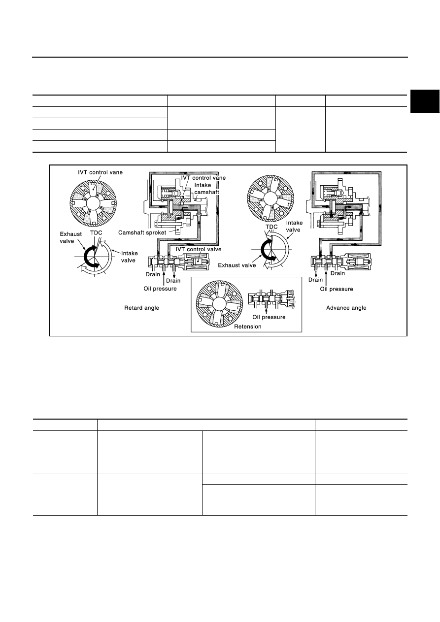
This mechanism hydraulically controls cam phases continuously with the fixed operating angle of the intake
valve.
The ECM receives signals such as crankshaft position, camshaft position, engine speed, and engine coolant
temperature. Then, the ECM sends ON/OFF pulse duty signals to the intake valve timing control solenoid
valve depending on driving status. This makes it possible to control the shut/open timing of the intake valve to
increase engine torque in low/mid speed range and output in high-speed range.

CONSULT-II Reference Value in Data Monitor Mode

ABS004BJ

Specification data are reference values.

Sensor

Input signal to ECM

ECM function

Actuator

Crankshaft position sensor (POS)

Engine speed and piston position

Intake valve 
timing control

Intake valve timing control 
solenoid valve

Camshaft position sensor (PHASE)

Engine coolant temperature sensor

Engine coolant temperature

Wheel sensor*

Vehicle speed

PBIB1389E

MONITOR ITEM

CONDITION

SPECIFICATION

INT/V TIM (B1)
INT/V TIM (B2)

Engine: After warming up

Shift lever: P or N

Air conditioner switch: OFF

No-load

Idle

5

°

 - 5

°

CA

2,000 rpm

Approx. 0

°

 - 30

°

CA

INT/V SOL (B1)
INT/V SOL (B2)

Engine: After warming up

Shift lever: P or N

Air conditioner switch: OFF

No-load

Idle

0% - 2%

2,000 rpm

Approx. 0% - 50%

EC-144

DTC P0011, P0021 IVT CONTROL

Revision: 2004 November

2004 Murano

On Board Diagnosis Logic

ABS004BK

FAIL-SAFE MODE

When the malfunction is detected, the ECM enters fail-safe mode.

DTC Confirmation Procedure

ABS004BL

CAUTION:

Always drive at a safe speed.

NOTE:

If DTC P0011 or P0021 is displayed with DTC P1111 or P1136, first perform trouble diagnosis for
DTC P1111 or P1136. Refer to 

EC-377

  .

If DTC Confirmation Procedure has been previously conducted, always turn ignition switch OFF and wait
at least 10 seconds before conducting the next test. 

TESTING CONDITION:
Before performing the following procedure, confirm that battery voltage is between 10V and 16V at
idle.

 WITH CONSULT-II

1.

Turn ignition switch ON and select “DATA MONITOR” mode with
CONSULT-II.

2.

Start engine and warm it up to the normal operating tempera-
ture.

3.

Maintain the following conditions for at least 6 consecutive sec-
onds.
Hold the accelerator pedal as steady as possible.

4.

Let engine idle for 10 seconds.

5.

If the 1st trip DTC is detected, go to 

EC-145, "Diagnostic Procedure"

  .

If the 1st trip DTC is not detected, go to next step.

6.

Maintain the following conditions for at least 20 consecutive seconds.

7.

If the 1st trip DTC is detected, go to 

EC-145, "Diagnostic Procedure"

  .

 WITH GST

Follow the procedure “WITH CONSULT-II” above.

DTC No.

Trouble diagnosis 

name

Detecting condition

Possible cause

P0011
0011
(Bank 1)

Intake valve timing 
control performance

There is a gap between angle of target and 
phase-control angle degree.

Crankshaft position sensor (POS)

Camshaft position sensor (PHASE)

Accumulation of debris to the signal pick-up 
portion of the camshaft

P0021
0021
(Bank 2)

Detected items

Engine operating condition in fail-safe mode

Intake valve timing control

The signal is not energized to the solenoid valve and the valve control does not function.

ENG SPEED

1,200 - 2,000 rpm (A constant rotation is maintained.)

COOLANT TEMPS

60 - 120

°

C (140 - 248

°

F)

Selector lever

P or N position

ENG SPEED

1,700 - 3,175 rpm (A constant rotation is maintained.)

COOLANT TEMPS

70 - 105

°

C (158 - 221

°

F)

Selector lever

1st or 2nd position

Driving location uphill

Driving vehicle uphill
(Increased engine load will help maintain the driving 
conditions required for this test.)

SEF353Z

DTC P0011, P0021 IVT CONTROL

EC-145

C

D

E

F

G

H

I

J

K

L

M

A

EC

Revision: 2004 November

2004 Murano

Diagnostic Procedure

ABS004BM

1. 

CHECK CRANKSHAFT POSITION SENSOR (POS)

Refer to 

EC-267, "Component Inspection"

  .

OK or NG

OK

>> GO TO 2.

NG

>> Replace crankshaft position sensor (POS).

2. 

CHECK CAMSHAFT POSITION SENSOR (PHASE)

Refer to 

EC-275, "Component Inspection"

  .

OK or NG

OK

>> GO TO 3.

NG

>> Replace camshaft position sensor (PHASE).

3. 

CHECK CAMSHAFT (INTAKE)

Check the following.

Accumulation of debris to the signal plate of camshaft rear end

Chipping signal plate of camshaft rear end

OK or NG

OK

>> GO TO 4.

NG

>> Remove debris and clean the signal plate of camshaft

rear end or replace camshaft.

4. 

CHECK INTERMITTENT INCIDENT

Refer to 

EC-130, "TROUBLE DIAGNOSIS FOR INTERMITTENT INCIDENT"

  .

For wiring diagram, refer to 

EC-263

   for CKP sensor (POS), 

EC-269

   an

EC-271

   for CMP sensor (PHASE).

>> INSPECTION END

SEC905C

EC-146

DTC P0037, P0038, P0057, P0058 HO2S2 HEATER

Revision: 2004 November

2004 Murano

DTC P0037, P0038, P0057, P0058 HO2S2 HEATER

PFP:226A0

Description

ABS004BV

SYSTEM DESCRIPTION

The ECM performs ON/OFF control of the heated oxygen sensor 2 heater corresponding to the engine speed,
amount of intake air and engine coolant temperature. 

OPERATION

CONSULT-II Reference Value in Data Monitor Mode

ABS004BW

Specification data are reference values.

On Board Diagnosis Logic

ABS004BX

Sensor

Input signal to ECM

ECM function

Actuator

Camshaft position sensor (PHASE)

Engine speed

Heated oxygen sensor 2 
heater control

Heated oxygen sensor 2 heater

Crankshaft position sensor (POS)

Engine coolant temperature sensor

Engine coolant temperature

Mass air flow sensor

Amount of intake air

Engine speed rpm

Heated oxygen sensor 2 heater

Above 3,600

OFF

Below 3,600 rpm after the following conditions are met.

Engine: After warming up

Keeping the engine speed between 3,500 and 4,000 rpm for 1 
minute and at idle for 1 minute under no load

ON

MONITOR ITEM

CONDITION

SPECIFICATION

HO2S2 HTR (B1)
HO2S2 HTR (B2)

Engine speed is below 3,600 rpm after the following conditions are met.

Engine: After warming up

Keeping the engine speed between 3,500 and 4,000 rpm for 1 minute and 
at idle for 1 minute under no load

ON

Engine speed: Above 3,600 rpm

OFF

DTC No.

Trouble diagnosis 

name

DTC detecting condition

Possible cause

P0037
0037
(Bank 1)

Heated oxygen 
sensor 2 heater 
control circuit low

The current amperage in the heated oxygen sen-
sor 2 heater circuit is out of the normal range.
(An excessively low voltage signal is sent to ECM 
through the heated oxygen sensor 2 heater.)

Harness or connectors
(The heated oxygen sensor 2 heater circuit is 
open or shorted.)

Heater oxygen sensor 2 heater

P0057
0057
(Bank 2)

P0038
0038
(Bank 1)

Heated oxygen 
sensor 2 heater 
control circuit high

The current amperage in the heated oxygen sen-
sor 2 heater circuit is out of the normal range.
(An excessively high voltage signal is sent to 
ECM through the heated oxygen sensor 2 
heater.)

Harness or connectors
(The heated oxygen sensor 2 heater circuit is 
shorted.)

Heater oxygen sensor 2 heater

P0058
0058
(Bank 2)

DTC P0037, P0038, P0057, P0058 HO2S2 HEATER

EC-147

C

D

E

F

G

H

I

J

K

L

M

A

EC

Revision: 2004 November

2004 Murano

DTC Confirmation Procedure

ABS004BY

NOTE:
If DTC Confirmation Procedure has been previously conducted, always turn ignition switch OFF and wait at
least 10 seconds before conducting the next test.
TESTING CONDITION:
Before performing the following procedure, confirm that battery voltage is between 11.0V and 16V at
idle.

 WITH CONSULT-II

1.

Turn ignition switch ON and select “DATA MONITOR” mode with CONSULT-II.

2.

Start engine and warm it up to the normal operating tempera-
ture.

3.

Turn ignition switch OFF and wait at least 10 seconds.

4.

Start the engine and keep the engine speed between 3,500 rpm
and 4,000 rpm for at least 1 minute under no load.

5.

Let engine idle for 1 minute.

6.

If 1st trip DTC is detected, go to 

EC-151, "Diagnostic Procedure"

.

 WITH GST

Follow the procedure “WITH CONSULT-II” above.

SEF176Y

EC-148

DTC P0037, P0038, P0057, P0058 HO2S2 HEATER

Revision: 2004 November

2004 Murano

Wiring Diagram

ABS004BZ

BANK 1

TBWA0687E

DTC P0037, P0038, P0057, P0058 HO2S2 HEATER

EC-149

C

D

E

F

G

H

I

J

K

L

M

A

EC

Revision: 2004 November

2004 Murano

Specification data are reference values and are measured between each terminal and ground.

CAUTION:

Do not use ECM ground terminals when measuring input/output voltage. Doing so may result in dam-
age to the ECM's transistor. Use a ground other than ECM terminals, such as the ground.

TER-

MINAL 

NO.

WIRE 

COLOR

ITEM

CONDITION

DATA (DC Voltage)

25

P/L

Heated oxygen sensor 2 
heater (bank 1)

[Engine is running]

Engine speed is below 3,600 rpm after the 
following conditions are met.

Engine: after warming up

Keeping the engine speed between 3,500 
and 4,000 rpm for 1 minute and at idle for 1 
minute under no load.

0 - 1.0V

[Ignition switch: ON]

Engine stopped

[Engine is running]

Engine speed is above 3,600 rpm.

BATTERY VOLTAGE
(11 - 14V)

EC-150

DTC P0037, P0038, P0057, P0058 HO2S2 HEATER

Revision: 2004 November

2004 Murano

BANK 2

TBWA0688E

DTC P0037, P0038, P0057, P0058 HO2S2 HEATER

EC-151

C

D

E

F

G

H

I

J

K

L

M

A

EC

Revision: 2004 November

2004 Murano

Specification data are reference values and are measured between each terminal and ground.

CAUTION:

Do not use ECM ground terminals when measuring input/output voltage. Doing so may result in dam-
age to the ECM's transistor. Use a ground other than ECM terminals, such as the ground.

Diagnostic Procedure

ABS004C0

1. 

CHECK GROUND CONNECTIONS

1.

Turn ignition switch OFF.

2.

Loosen and retighten two ground screws on the body.
Refer to 

EC-139, "Ground Inspection"

 .

OK or NG

OK

>> GO TO 2.

NG

>> Repair or replace ground connections.

TER-

MINAL 

NO.

WIRE 

COLOR

ITEM

CONDITION

DATA (DC Voltage)

6

L/R

Heated oxygen sensor 2 
heater (bank 2)

[Engine is running]

Engine speed is below 3,600 rpm after the 
following conditions are met.

Engine: after warming up

Keeping the engine speed between 3,500 
and 4,000 rpm for 1 minute and at idle for 1 
minute under no load.

0 - 1.0V

[Ignition switch: ON]

Engine stopped

[Engine is running]

Engine speed is above 3,600 rpm.

BATTERY VOLTAGE
(11 - 14V)

PBIB1835E

EC-152

DTC P0037, P0038, P0057, P0058 HO2S2 HEATER

Revision: 2004 November

2004 Murano

2. 

CHECK HO2S2 POWER SUPPLY CIRCUIT

1.

Disconnect heated oxygen sensor 2 harness connector.

2.

Turn ignition switch ON.

3.

Check voltage between HO2S2 terminal 3 and ground with
CONSULT-II or tester.

OK or NG

OK

>> GO TO 7.

NG

>> GO TO 3.

3. 

CHECK CONDENSER CIRCUIT-I

1.

Turn ignition switch OFF.

2.

Disconnect fuse block (J/B) harness connector M1.

3.

Check resistance between fuse block (J/B) terminal 9A and ground.
Refer to Wiring Diagram. 

4.

Also check harness for short to ground and short to power.

OK or NG

OK

>> GO TO 4.

NG

>> GO TO 5.

4. 

DETECT MALFUNCTIONING PART

Check the following.

Harness connectors M82, F102

Fuse block (J/B) connector M1

15A fuse

Harness for open or short between heated oxygen sensor 2 and fuse

>> Repair harness or connectors.

PBIB1352E

Voltage: Battery voltage

PBIB0112E

Resistance: Above 1M

 at 25

°

C (77

°

F)

DTC P0037, P0038, P0057, P0058 HO2S2 HEATER

EC-153

C

D

E

F

G

H

I

J

K

L

M

A

EC

Revision: 2004 November

2004 Murano

5. 

CHECK CONDENSER CIRCUIT-II

1.

Disconnect condenser harness connectors.

2.

Check harness continuity between fuse block (J/B) terminal 9A and condenser terminal 1, condenser ter-
minal 2 and ground.
Refer to Wiring Diagram. 

3.

Also check harness for short to ground and short to power.

OK or NG

OK

>> GO TO 6.

NG

>> 1. Repair harness or connectors.

2. Check 15A fuse. If NG, replace fuse.

6. 

CHECK CONDENSER

Refer to 

EC-154, "Component Inspection"

 .

OK or NG

OK

>> GO TO 9.

NG

>> Replace condenser.

7. 

CHECK HO2S2 OUTPUT SIGNAL CIRCUIT FOR OPEN AND SHORT

1.

Turn ignition switch OFF.

2.

Disconnect ECM harness connector.

3.

Check harness continuity between ECM terminal and HO2S2 terminal as follows.
Refer to Wiring Diagram.

4.

Also check harness for short to ground and short to power.

OK or NG

OK

>> GO TO 8.

NG

>> Repair open circuit or short to ground or short to power in harness or connectors.

8. 

CHECK HEATED OXYGEN SENSOR 2 HEATER

Refer to 

EC-154, "Component Inspection"

 .

OK or NG

OK

>> GO TO 9.

NG

>> Replace malfunctioning heated oxygen sensor 2.

9. 

CHECK INTERMITTENT INCIDENT

Refer to 

EC-130, "TROUBLE DIAGNOSIS FOR INTERMITTENT INCIDENT"

 .

>> INSPECTION END

Continuity should exist.

DTC

Terminals

Bank

ECM

Sensor

P0037, P0038

25

2

1

P0057, P0058

6

2

2

Continuity should exist.

EC-154

DTC P0037, P0038, P0057, P0058 HO2S2 HEATER

Revision: 2004 November

2004 Murano

Component Inspection

ABS004C1

HEATED OXYGEN SENSOR 2 HEATER

1.

Check resistance between HO2S2 terminals as follows.

2.

If NG, replace heated oxygen sensor 2.

CAUTION:

Discard any heated oxygen sensor which has been dropped
from a height of more than 0.5 m (19.7 in) onto a hard sur-
face such as a concrete floor; use a new one.

Before installing new oxygen sensor, clean exhaust system
threads using Oxygen Sensor Thread Cleaner tool J-43897-
18 or J-43897-12 and approved anti-seize lubricant.

CONDENSER

1.

Turn ignition switch OFF.

2.

Disconnect condenser harness connector.

3.

Check resistance between condenser terminals 1 and 2.

Removal and Installation

ABS004C2

HEATED OXYGEN SENSOR 2

Refer to 

EM-23, "EXHAUST MANIFOLD AND THREE WAY CATALYST"

 .

Terminal No.

Resistance

2 and 3

5.0 - 7.0 

 at 25

°

C (77

°

F)

1 and 2, 3, 4


(Continuity should not exist)

4 and 1, 2, 3

SEF249Y

Resistance

Above 1 M

 at 25

°

C (77

°

F)

PBIB0794E

DTC P0101 MAF SENSOR

EC-155

C

D

E

F

G

H

I

J

K

L

M

A

EC

Revision: 2004 November

2004 Murano

DTC P0101 MAF SENSOR

PFP:22680

Component Description

ABS004C3

The mass air flow sensor is placed in the stream of intake air. It mea-
sures the intake flow rate by measuring a part of the entire intake
flow. The mass air flow sensor controls the temperature of the hot
wire to a certain amount. The heat generated by the hot wire is
reduced as the intake air flows around it. The more air, the greater
the heat loss. 
Therefore, the electric current supplied to hot wire is changed to
maintain the temperature of the hot wire as air flow increases. The
ECM detects the air flow by means of this current change.

CONSULT-II Reference Value in Data Monitor Mode

ABS004C4

Specification data are reference values.

On Board Diagnosis Logic

ABS004C5

This self-diagnosis has the one trip detection logic.

PBIB1604E

MONITOR ITEM

CONDITION

SPECIFICATION

MAS A/F SE-B1

See 

EC-126, "TROUBLE DIAGNOSIS - SPECIFICATION VALUE"

 .

CAL/LD VALUE

Engine: After warming up

Shift lever: P or N

Air conditioner switch: OFF

No-load

Idle

5% - 35%

2,500 rpm

5% - 35%

MASS AIRFLOW

Engine: After warming up

Shift lever: P or N

Air conditioner switch: OFF

No-load

Idle

2.0 - 6.0 g·m/s

2,500 rpm

7.0 - 20.0 g·m/s

DTC No.

Trouble diagnosis name

DTC detecting condition

Possible cause

P0101
0101

Mass air flow sensor cir-
cuit range/performance 
problem

A)

A high voltage from the sensor is sent to ECM 
under light load driving condition.

Harness or connectors
(The sensor circuit is open or 
shorted.)

Mass air flow sensor

B)

A low voltage from the sensor is sent to ECM 
under heavy load driving condition.

Harness or connectors
(The sensor circuit is open or 
shorted.)

Intake air leaks

Mass air flow sensor

EC-156

DTC P0101 MAF SENSOR

Revision: 2004 November

2004 Murano

DTC Confirmation Procedure

ABS004C6

Perform PROCEDURE FOR MALFUNCTION A first.
If the DTC cannot be confirmed, perform PROCEDURE FOR MALFUNCTION B.
NOTE:
If DTC Confirmation Procedure has been previously conducted, always turn ignition switch OFF and wait at
least 10 seconds before conducting the next test.

PROCEDURE FOR MALFUNCTION A

NOTE:
If engine will not start or stops soon, wait at least 10 seconds with engine stopped (Ignition switch ON) instead
of running engine at idle speed.

 With CONSULT-II

1.

Turn ignition switch ON.

2.

Select “DATA MONITOR” mode with CONSULT-II.

3.

Start engine and warm it up to normal operating temperature.

4.

Run engine for at least 10 seconds at idle speed.

5.

If DTC is detected, go to 

EC-159, "Diagnostic Procedure"

 .

 With GST

Follow the procedure “With CONSULT-II” above.

PROCEDURE FOR MALFUNCTION B

CAUTION:

Always drive vehicle at a safe speed.

 With CONSULT-II 

1.

Turn ignition switch ON.

2.

Start engine and warm it up to normal operating temperature.
If engine cannot be started, go to 

EC-159, "Diagnostic Procedure"

 .

3.

Select “DATA MONITOR” mode with CONSULT-II.

4.

Check the voltage of “MAS A/F SE-B1” with “DATA MONITOR”.

5.

Increases engine speed to about 4,000 rpm.

6.

Monitor the linear voltage rise in response to engine speed
increases.
If NG, go to 

EC-159, "Diagnostic Procedure"

 .

If OK, go to following step.

SEF174Y

SEF243Y

DTC P0101 MAF SENSOR

EC-157

C

D

E

F

G

H

I

J

K

L

M

A

EC

Revision: 2004 November

2004 Murano

7.

Maintain the following conditions for at least 10 consecutive sec-
onds.

8.

If DTC is detected, go to 

EC-159, "Diagnostic Procedure"

 .

Overall Function Check

ABS004C7

PROCEDURE FOR MALFUNCTION B

Use this procedure to check the overall function of the mass air flow sensor circuit. During this check, a DTC
might not be confirmed.

 With GST

1.

Start engine and warm it up to normal operating temperature.

2.

Select MODE 1 with GST.

3.

Check the mass air flow sensor signal with MODE 1.

4.

Check for linear mass air flow sensor signal value rise in
response to increases to about 4,000 rpm in engine speed.

5.

If NG, go to 

EC-159, "Diagnostic Procedure"

 .

ENG SPEED

More than 2,000 rpm

THRTL SEN 1

More than 3V

THRTL SEN 2

More than 3V

Selector lever

Suitable position

Driving location

Driving vehicle uphill (Increased engine load) will help 
maintain the driving conditions required for this test.

PBIB0199E

SEF534P

EC-158

DTC P0101 MAF SENSOR

Revision: 2004 November

2004 Murano

Wiring Diagram

ABS004C8

TBWA0689E


Content      ..     75      76      77      78     ..