Nissan Murano Z50 (2004 year). Manual - part 76
TROUBLE DIAGNOSIS - SPECIFICATION VALUE
EC-127
C
D
E
F
G
H
I
J
K
L
M
A
EC
Revision: 2004 November
2004 Murano
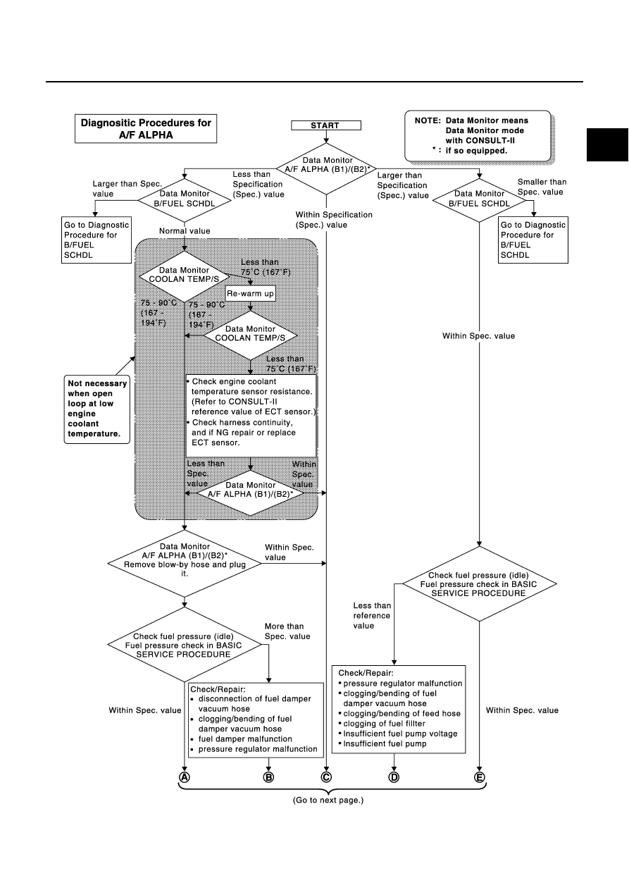
Diagnostic Procedure
ABS004B8
SEF613ZD
|
|
|
TROUBLE DIAGNOSIS - SPECIFICATION VALUE EC-127 C D E F G H I J K L M A EC Revision: 2004 November 2004 Murano Diagnostic Procedure ABS004B8 SEF613ZD |