Nissan Murano Z50 (2004 year). Manual - part 63


  Index      Manuals     Nissan Murano Z50 (2004 year) - Service and Repair Manual


Search            copyright infringement  


Content      ..     61      62      63      64     ..


Nissan Murano Z50 (2004 year). Manual - part 63


TRANSAXLE ASSEMBLY

CVT-227

D

E

F

G

H

I

J

K

L

M

A

B

CVT

Revision: 2004 November

2004 Murano

12. Remove transfer assembly. Refer to 

TF-51, "Removal and Installation"

 . (AWD models)

CAUTION:

Be sure to replace the new differential side oil seal (converter housing side only) every removal of
transfer. Refer to 

CVT-218, "Removal and Installation"

 . 

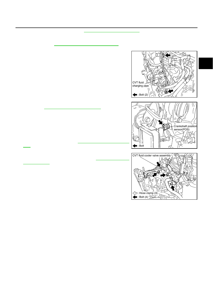
13. Remove CVT fluid charging pipe.

14. Remove O-ring from CVT fluid charging pipe.

15. Disconnect harness connector and wire harness.

16. Remove crankshaft position sensor (POS), from engine assem-

bly. Refer to 

EM-28, "Removal and Installation"

 .

CAUTION:

Do not subject it to impact by dropping or hitting it.

Do not disassemble.

Do not allow metal filings, etc., to get on the sensor's
front edge magnetic area.

Do not place in an area affected by magnetism.

17. Remove starter motor. Refer to 

SC-15, "Removal and Installa-

tion"

 .

18. Remove CVT fluid cooler valve assembly. (With CVT fluid cooler

tube assembly and heater hose). Refer to 

CVT-220, "Removal

and Installation"

 .

SCIA1894E

SCIA6884E

SCIA6885E

CVT-228

TRANSAXLE ASSEMBLY

Revision: 2004 November

2004 Murano

19.  Install slinger to transaxle assembly.

20. Remove rear gusset.

21. Remove LH engine mounting bracket and LH engine mounting

insulator.

22.  Remove front suspension member from transaxle assembly

and engine assembly. Refer to 

EM-105, "Removal and Installa-

tion"

 . (AWD models)

23.  Remove transaxle assembly fixing bolts with power tool.

24.  Remove transaxle assembly from engine assembly with a hoist.

Secure torque converter to prevent it from dropping.

INSPECTION
Installation and Inspection of Torque Converter

After inserting a torque converter to a transaxle, be sure to
check dimension “A” to ensure it is within the reference value
limit.

SCIA4355E

SCIA1868E

Dimension “A”:

14.0 mm (0.55 in) or more

SCIA2137E

TRANSAXLE ASSEMBLY

CVT-229

D

E

F

G

H

I

J

K

L

M

A

B

CVT

Revision: 2004 November

2004 Murano

INSTALLATION

Install the removed parts in the reverse order of the removal, while paying attention to the following work.

Screw and set the locate into the stud bolts for the torque con-
verter locate.

Rotate the torque converter for the locate to go down.

Rotate the drive plate for the hole of the drive plate locate to go
down.

Installing transaxle assembly from engine assembly with a hoist.

SCIA1871E

SCIA6881E

SCIA1872E

SCIA1868E

CVT-230

TRANSAXLE ASSEMBLY

Revision: 2004 November

2004 Murano

When installing fluid cooler tube to transaxle assembly, tran-
saxle assembly the part with the tube aligned with the rib. 

When installing transaxle to the engine, attach the fixing bolts in
accordance with the following standard.

Align the positions of tightening nuts for drive plate with those of
the torque converter, and temporarily tighten the nuts. Then,
tighten the nuts with the specified torque.

CAUTION:

When turning crankshaft, turn it clockwise as viewed
from the front of the engine.

When tightening the tightening nuts for the torque con-
verter after fixing the crankshaft pulley bolts, be sure to
confirm the tightening torque of the crankshaft pulley
mounting bolts. Refer to 

EM-66, "INSTALLATION"

 .

After converter is installed to drive plate, rotate crankshaft several turns and check to be sure
that transaxle rotates freely without binding.

Install POS sensor. Refer to 

EM-28, "Removal and Installation"

 .

After completing installation, check for fluid leakage, fluid level, and the positions of CVT. Refer to 

CVT-14,

"Checking CVT Fluid"

 , 

CVT-209, "Adjustment of CVT Position"

 , 

CVT-209, "Checking of CVT Position"

 .

When replacing the CVT assembly, erase EEP ROM in TCM. Refer to 

CVT-8, "Precautions for TCM and

CVT Assembly Replacement"

 .

SCIA2285E

Bolt No.

1

2

 3

4

Number of bolts

 1

2

 2

4

Bolt length

 “

”mm (in)

 52 (2.05)

 36 (1.42)

 105 (4.13)

 35 (1.38)

Tightening torque
N·m (kg-m, ft-lb)

75 (7.7, 55)

47 (4.8, 35)

SCIA6882E

: 51N-m (5.2kg-m, 38ft-lb)

SCIA1861E

SERVICE DATA AND SPECIFICATIONS (SDS)

CVT-231

D

E

F

G

H

I

J

K

L

M

A

B

CVT

Revision: 2004 November

2004 Murano

SERVICE DATA AND SPECIFICATIONS (SDS)

PFP:00030

General Specifications

ACS001ZX

*1: Refer to 

MA-11, "Fluids and Lubricants"

 .

Vehicle Speed When Shifting Gears

ACS004ZY

Numerical value data are reference values.

*: Without manual mode

CAUTION:

Lock-up clutch is engaged when vehicle speed is approximately 18 km/h (11 MPH) to 90 km/h (56 MPH).

Stall Speed

ACS00201

Line Pressure

ACS00A26

*

1

 : Without manual mode

*

2

 : Reference values

Applied model

VQ35DE engine

2WD

AWD

CVT model

RE0F09A

CVT assembly

Model code number

1XD07

1XD15

1XD08

1XD16

transmission gear ratio

D range

Variable

Reverse

1.766

Final drive

5.173

Recommended fluid

NISSAN CVT fluid NS-2*1

Fluid capacity

10.2 liter (10-6/8 US qt, 9 Imp qt)

CAUTION:

Use only Genuine Nissan CVT fluid NS-2. Do not mix with other fluid.

Using CVT fluid other than Genuine NISSAN CVT fluid NS-2 will deteriorate in driveability and CVT durability, and may 
damage the CVT, which is not covered by the warranty.

Engine type

 Throttle position

Shift pattern

Engine speed (rpm)

At 40 km/h (25 MPH)

At 60 km/h (37 MPH)

VQ35DE

8/8

“D” position

Second position*

“L” position*

 2,800 - 4,300

 3,900 - 5,300

2/8

“D” position

 1,200 - 2,000

 1,300 - 2,100

Second position*

 2,200 - 3,000

 2,800 - 3,600

“L” position*

 2,800 - 3,600

 3,800 - 4,600

Stall speed 

 2,700 - 3,250 rpm

Engine

Engine speed

Line pressure

kPa (kg/cm

2

 , psi)

“R”, “D”, “L”*

1

  positions

VQ35DE

At idle speed

 750 (7.65, 108.8)

At stall speed

 5,300 - 5,700 (54.06 - 58.14, 768.5 - 826.5)*

2

CVT-232

SERVICE DATA AND SPECIFICATIONS (SDS)

Revision: 2004 November

2004 Murano

Solenoid Valves

ACS00339

CVT Fluid Temperature Sensor

ACS002SC

Primary Speed Sensor

ACS002SD

Secondary Speed Sensor

ACS002SE

Removal and Installation

ACS002SG

Name

Resistance (Approx.) (

)

Terminal

Pressure control solenoid valve B (Secondary 
pressure solenoid valve)

3 - 9

3

Pressure control solenoid valve A (Line pressure 
solenoid valve)

2

Torque converter clutch solenoid valve

12

Lock-up select solenoid valve

6 - 19

13

Name

Condition

CONSULT-II “DATA MONITOR” (Approx.) (V)

Resistance (Approx.) (k

)

CVT fluid temperature sensor

20

°

C (68

°

F)

 2.0

6.5

80

°

C (176

°

F)

 1.0

 0.9

Name

Condition

Data (Approx.)

Primary speed sensor

When driving [“D” position, 20 km/h (12 MPH)].

600 (Hz)

Name

Condition

Data (Approx.)

Secondary speed sensor

When driving [“D” position, 20 km/h (12 MPH)].

 300 (Hz)

Distance between end of converter housing and torque converter 

 14.0 mm (0.55 in) or more

DI-1

DRIVER INFORMATION SYSTEM

K  ELECTRICAL

CONTENTS

C

D

E

F

G

H

I

J

L

M

SECTION 

DI

A

B

DI

Revision: 2004 November

2004 Murano

DRIVER INFORMATION SYSTEM

PRECAUTION ............................................................ 3

Precautions for Supplemental Restraint System 
(SRS) “AIR BAG” and “SEAT BELT PRE-TEN-
SIONER” .................................................................. 3
Wiring Diagrams and Trouble Diagnosis .................. 3

COMBINATION METERS ........................................... 4

System Description  .................................................. 4

UNIFIED METER CONTROL UNIT  ...................... 4
UNIFIED METER AND A/C AMP.  ......................... 4
HOW TO CHANGE THE DISPLAY FOR ODO/
TRIP METER  ........................................................ 5
POWER SUPPLY AND GROUND CIRCUIT  ........ 6
WATER TEMPERATURE GAUGE ........................ 6
TACHOMETER ..................................................... 6
FUEL GAUGE  ....................................................... 6
SPEEDOMETER ................................................... 6

Component Parts and Harness Connector Location 

..... 7

Combination Meter ................................................... 8

CHECK .................................................................. 8

Circuit Diagram  ........................................................ 9
Wiring Diagram — METER — ................................ 10
Terminals and Reference Value for Combination 
Meter ...................................................................... 12
Terminals and Reference Value for Unified Meter 
and A/C Amp. ......................................................... 13
Meter/Gauge Operation and Odo/Trip Meter  ......... 14

SELF-DIAGNOSIS FUNCTION  .......................... 14
HOW TO ALTERNATE DIAGNOSIS MODE  ....... 14

CONSULT-II Function  ............................................ 14
How to Proceed With Trouble Diagnosis ................ 15
Diagnosis Flow ....................................................... 15
Power Supply and Ground Circuit Inspection  ........ 16
Symptom Chart 1  ................................................... 18
Symptom Chart 2  ................................................... 18
Vehicle Speed Signal Inspection  ............................ 19
Engine Speed Signal Inspection  ............................ 20
Water Temperature Signal Inspection  .................... 21
Fuel Level Sensor Signal Inspection 1  ................... 22

FUEL GAUGE  ..................................................... 22

Fuel Level Sensor Signal Inspection 2  ................... 23

LOW-FUEL WARNING LAMP  ............................. 23

CAN Communication System Inspection ................ 23
Communication Line Inspection  ............................. 23
Odo/Trip Meter and Illumination Control Switch 
Inspection ............................................................... 26
Fuel Gauge Pointer Fluctuates, Indicator Wrong 
Value or Varies  ....................................................... 27
Fuel Gauge Does Not Move to Full-position ........... 27
Electrical Components Inspection  .......................... 28

FUEL LEVEL SENSOR UNIT CHECK  ................ 28

Removal and Installation of Combination Meter  ..... 28

REMOVAL ........................................................... 28
INSTALLATION ................................................... 28

Disassembly and Assembly of Combination Meter ... 29

DISASSEMBLY ................................................... 29
ASSEMBLY ......................................................... 30

UNIFIED METER AND A/C AMP .............................. 31

System Description ................................................. 31

INPUT/OUTPUT SIGNALS  ................................. 31
FAIL-SAFE .......................................................... 32

CAN Communication System Description  .............. 33
CAN Communication Unit ....................................... 33
Schematic ............................................................... 34
CONSULT-II Function ............................................. 35

CONSULT-II BASIC OPERATION  ....................... 35
SELF-DIAGNOSTIC RESULTS ........................... 36
DATA MONITOR  ................................................. 36

Removal and Installation of Unified Meter and A/C 
Amp. ....................................................................... 38

REMOVAL ........................................................... 38
INSTALLATION ................................................... 38

COMPASS ................................................................. 39

System Description ................................................. 39

DIRECTION DISPLAY ......................................... 39

Wiring Diagram – COMPAS –  ................................ 41
Removal and Installation of Compass  .................... 42

WARNING LAMPS .................................................... 43

Schematic ............................................................... 43
Wiring Diagram — WARN — .................................. 44
Oil Pressure Warning Lamp Stays Off (Ignition 

DI-2

Revision: 2004 November

2004 Murano

Switch ON)  ............................................................. 51
Oil Pressure Warning Lamp Does Not Turn Off (Oil 
Pressure Is Normal) ................................................ 52
Component Inspection ............................................ 53

OIL PRESSURE SWITCH ................................... 53

CVT INDICATOR  ....................................................... 54

Wiring Diagram — CVTIND —  ............................... 54
CVT Indicator Does Not Illuminate  ......................... 58

WARNING CHIME ..................................................... 60

Component Parts and Harness Connector Location ... 60
System Description ................................................. 60

FUNCTION .......................................................... 60
IGNITION KEY WARNING CHIME ...................... 61
LIGHT WARNING CHIME  ................................... 61
SEAT BELT WARNING CHIME  ........................... 61

CAN Communication System Description  .............. 62
CAN Communication Unit ....................................... 62
Wiring Diagram — CHIME —  ................................. 63
Terminals and Reference Value for BCM ................ 65
Terminals and Reference Value for Unified Meter 
and A/C Amp.  ......................................................... 66

Terminals and Reference Value for Combination 
Meter .......................................................................67
How to Proceed With Trouble Diagnosis  ................67
Preliminary Check  ...................................................68

INSPECTION FOR POWER SUPPLY AND 
GROUND CIRCUIT  .............................................68

CONSULT-II Function  .............................................69

DIAGNOSTIC ITEMS DESCRIPTION  .................69
CONSULT-II BASIC OPERATION PROCEDURE 

...69

DATA MONITOR  ..................................................70
ACTIVE TEST ......................................................70
SELF-DIAGNOSTIC RESULTS  ...........................70

All Warnings Are Not Operated ...............................71
Key Warning Chime and Light Warning Chime Does 
Not Operate (Seat belt Warning Chime Does Oper-
ate) ..........................................................................71
Key Warning Chime Does Not Operate  ..................72
Light Warning Chime Does Not Operate .................74
Seat Belt Warning Chime Does Not Operate ..........75

PRECAUTION

DI-3

C

D

E

F

G

H

I

J

L

M

A

B

DI

Revision: 2004 November

2004 Murano

PRECAUTION 

PFP:00011

Precautions for Supplemental Restraint System (SRS) “AIR BAG” and “SEAT 
BELT PRE-TENSIONER”

AKS004FR

The Supplemental Restraint System such as “AIR BAG” and “SEAT BELT PRE-TENSIONER”, used along
with a front seat belt, helps to reduce the risk or severity of injury to the driver and front passenger for certain
types of collision. This system includes seat belt switch inputs and dual stage front air bag modules. The SRS
system uses the seat belt switches to determine the front air bag deployment, and may only deploy one front
air bag, depending on the severity of a collision and whether the front occupants are belted or unbelted.
Information necessary to service the system safely is included in the SRS and SB section of this Service Man-
ual.

WARNING:

To avoid rendering the SRS inoperative, which could increase the risk of personal injury or death
in the event of a collision which would result in air bag inflation, all maintenance must be per-
formed by an authorized NISSAN/INFINITI dealer.

Improper maintenance, including incorrect removal and installation of the SRS, can lead to per-
sonal injury caused by unintentional activation of the system. For removal of Spiral Cable and Air
Bag Module, see the SRS section.

Do not use electrical test equipment on any circuit related to the SRS unless instructed to in this
Service Manual. SRS wiring harnesses can be identified by yellow and/or orange harnesses or
harness connectors.

Wiring Diagrams and Trouble Diagnosis 

AKS004FT

When you read wiring diagrams, refer to the following:

Refer to 

GI-14, "How to Read Wiring Diagrams"

  .

Refer to 

PG-3, "POWER SUPPLY ROUTING CIRCUIT"

   for power distribution circuit.

When you perform trouble diagnosis, refer to the following:

Refer to 

GI-10, "HOW TO FOLLOW TEST GROUPS IN TROUBLE DIAGNOSES"

  .

Refer to 

GI-26, "How to Perform Efficient Diagnosis for an Electrical Incident"

  .

DI-4

COMBINATION METERS

Revision: 2004 November

2004 Murano

COMBINATION METERS

PFP:24814

System Description

AKS004FU

UNIFIED METER CONTROL UNIT

Speedometer, odo/trip meter, tachometer, fuel gauge and water temperature gauge are controlled by the
unified meter control unit, which is built into the combination meter. Unified meter control unit receives sig-
nals from unified meter and A/C amp.

Warning lamp and indicator lamp of combination meter are controlled by signals drawn from the unified
meter and A/C amp.

Digital meter is adopted for odo/trip meter.*
*The record of the odo meter is kept even if the battery cable is disconnected. The record of the trip meter
is erased when the battery cable is disconnected.

Odo/trip meter and CVT indicator segments can be checked in diagnosis mode.

Meters/gauges can be checked in diagnosis mode.

Illumination Control 

The unified meter control unit outputs the odo/trip meter and CVT
indicator lighting when the ignition switch is turned on. When the
lighting switch is turned on, light on for the combination meter dial,
odo/trip meter and illumination control switch and external lighting
are output. In addition, when the lighting switch is turned on, the illu-
mination control switch on the left side of the combination meter can
be used to adjust the brightness of each light. The brightness can be
adjusted to sixteen different levels: From 0 (no lights) to 15 (maxi-
mum). Pressing the illumination control switch will brighten or darken
the lights. When the key switch is in the START position, the combi-
nation meter dial lighting and illumination control switch lighting are
turned off.

UNIFIED METER AND A/C AMP.

Refer to 

DI-31, "System Description"

  in “UNIFIED METER AND A/C AMP”.

PKIA2478E

COMBINATION METERS

DI-5

C

D

E

F

G

H

I

J

L

M

A

B

DI

Revision: 2004 November

2004 Murano

HOW TO CHANGE THE DISPLAY FOR ODO/TRIP METER

The vehicle speed signal and the memory signals from the meter memory circuit are processed by the
combination meter and the mileage is displayed.

Depressing the odo/trip meter switch toggles the mode in the following order.

The odo/trip meter display mode toggling and trip display reset-
ting can be identified by the amount of time that elapses from
pressing the odo/trip meter switch to releasing it.

When resetting with trip A displayed, only trip A display is reset
(Trip B operates the same way).

SEL175W

PKIA2480E

DI-6

COMBINATION METERS

Revision: 2004 November

2004 Murano

POWER SUPPLY AND GROUND CIRCUIT

Power is supplied at all times

through 10A fuse [No. 19, located in the fuse block (J/B)]

to unified meter and A/C amp. terminal 21

through 10A fuse [No. 21, located in the fuse block (J/B)]

to combination meter terminal 21.

With the ignition switch in the ON or START position, power is supplied

through 10A fuse [No. 14, located in the fuse block (J/B)]

to combination meter terminal 20

through 10A fuse [No. 12, located in the fuse block (J/B)]

to unified meter and A/C amp. terminal 22.

With the ignition switch in the ON position, power is supplied

through 15A fuse [No. 10, located in the fuse block (J/B)], and

through 15A fuse [No. 11, located in the fuse block (J/B)]

to unified meter and A/C amp. terminal 46.

Ground is supplied

to combination meter terminals 22, 23 and 24

through body grounds M14 and M78

to unified meter and A/C amp. terminals 29 and 30

through body grounds M14 and M78.

WATER TEMPERATURE GAUGE

The water temperature gauge indicates the engine coolant temperature.
ECM provides a engine coolant temperature signal to unified meter and A/C amp. with CAN communication
line. Unified meter and A/C amp. provides a water temperature signal to combination meter for water temper-
ature gauge with communication line between unified meter and A/C amp. and combination meter.

TACHOMETER

The tachometer indicates engine speed in revolutions per minute (rpm).
ECM provides an engine speed signal to unified meter and A/C amp. with CAN communication line. Unified
meter and A/C amp. provides an engine speed signal to combination meter for tachometer with communica-
tion line between unified meter and A/C amp. and combination meter.

FUEL GAUGE

The fuel gauge indicates the approximate fuel level in the fuel tank.
The fuel gauge is regulated by a variable ground signal supplied

from unified meter and A/C amp. terminal 36

through the fuel level sensor unit and fuel pump (main) terminals 5 and 7, and

through the fuel level sensor unit (sub), and

through the fuel level sensor unit and fuel pump (main) terminals 6 and 2

to unified meter and A/C amp. terminal 28 for the fuel gauge.

Unified meter and A/C amp. provides an fuel level signal to combination meter for fuel gauge with communica-
tion line between unified meter and A/C amp. and combination meter.

SPEEDOMETER

ABS actuator and electric unit (control unit) provides a vehicle speed signal to the unified meter and A/C amp.
with CAN communication line. After unified meter and A/C amp. received the vehicle speed signal, it changes
the signal to 8 pulse signal and provides the 8 pulse signal to the combination meter for the speedometer.

COMBINATION METERS

DI-7

C

D

E

F

G

H

I

J

L

M

A

B

DI

Revision: 2004 November

2004 Murano

Component Parts and Harness Connector Location

AKS004FV

PKIA2477E

DI-8

COMBINATION METERS

Revision: 2004 November

2004 Murano

Combination Meter

AKS004FW

CHECK

SKIA9196E

COMBINATION METERS

DI-9

C

D

E

F

G

H

I

J

L

M

A

B

DI

Revision: 2004 November

2004 Murano

Circuit Diagram

AKS004FX

TKWA0814E

DI-10

COMBINATION METERS

Revision: 2004 November

2004 Murano

Wiring Diagram — METER —

AKS004FY

TKWA1157E


Content      ..     61      62      63      64     ..