Nissan Murano Z50 (2004 year). Manual - part 55
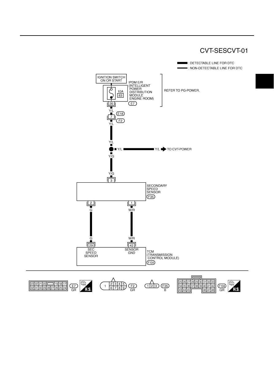
DTC P0720 VEHICLE SPEED SENSOR CVT (SECONDARY SPEED SENSOR)
CVT-99
D
E
F
G
H
I
J
K
L
M
A
B
CVT
Revision: 2004 November
2004 Murano
Wiring Diagram — CVT — SESCVT
ACS002IQ
TCWA0248E
|
|
|
DTC P0720 VEHICLE SPEED SENSOR CVT (SECONDARY SPEED SENSOR) CVT-99 D E F G H I J K L M A B CVT Revision: 2004 November 2004 Murano Wiring Diagram — CVT — SESCVT ACS002IQ TCWA0248E |